Catheter Delivery System For Stent Valve

a technology of stent valve and catheter, which is applied in the field of catheter delivery systems for stent valves, can solve the problems of poor valve functioning, valve regurgitation, valve prolapse and/or coronary occlusion, etc., and achieve the effect of convenient accurate positioning and deployment of stent valves, and simple and effective us

Active Publication Date: 2013-09-05
BOSTON SCI LTD
View PDF51 Cites 21 Cited by
  • Summary
  • Abstract
  • Description
  • Claims
  • Application Information

AI Technical Summary

Benefits of technology

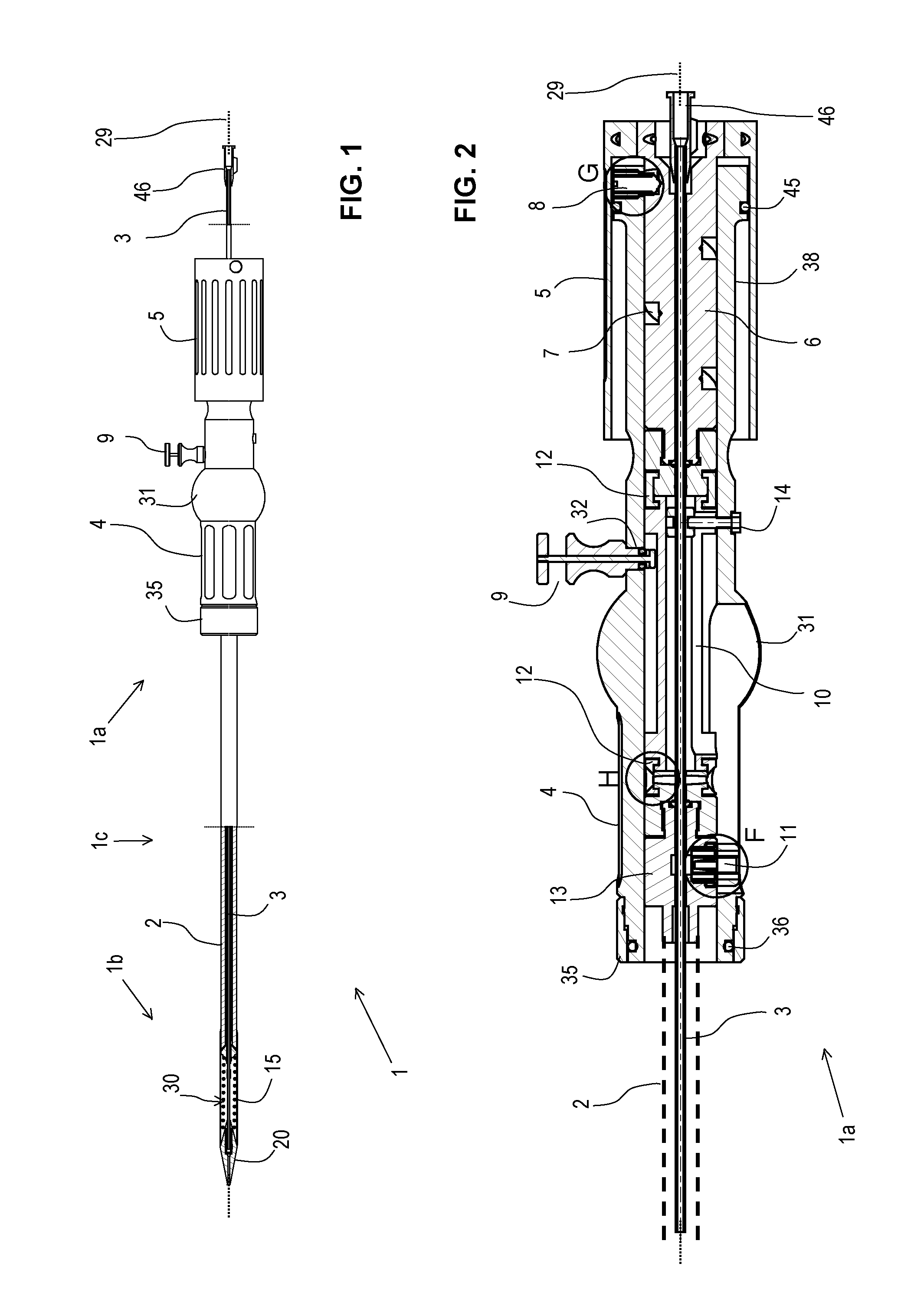
[0009]In some embodiments, the actuator is configured to drive translation of the sheath from a (e.g. fully) closed position to a (e.g. fully) open position by three complete turns or less of the rotary control, optionally two complete turns or less (measured in quarter turns, e.g., ¼ turn, ½ turn, complete turn, etc.). The translation of the sheath may be at least 50 mm, or at least 60 mm, or at least 70 mm. Such a relatively large translation of the sheath for relatively few turns of the rotary control may involve a relatively coarse thread pitch of a threaded element for converting the rotary movement into linear translational movement. The delivery catheter may optionally comprise a friction member for resisting rotation of the rotary control. The friction member may comprise a protuberance or member carried on at least one of confronting surfaces of a handle housing and the rotary control. For example, the friction member may be provided on an outer surface of the handle housing, and / or an inner surface of the rotary control. Such positioning can provide a relatively large friction-generating contact area, facilitate ease of construction and provide predictable control of the amount of friction generated. In some embodiments, the friction member comprises an O-ring, for example, of elastomeric material.
[0088]Such a method can address an issue of the sheath, when abutting the tip member, potentially limiting the freedom of the tip member to flex. By partly displacing the sheath from the tip member, at least after having penetrated the heart and / or vascular system, the tip member can be allowed more freedom to flex at the expense of reduced support. This can be used to assist advancement of the distal portion without deploying the stent. For example, for a transapical delivery catheter, by partly displacing the sheath from the tip member after having penetrated the ventricle (such as after having passed through an existing valve), the tip member can be allowed more freedom to flex. This can assist introduction and / or advancement of the distal portion in the ascending aorta and / or in the aortic arch, especially in cases where a person's individual anatomy may make such advancement difficult.

Problems solved by technology

Specifically, if the replacement valve is not placed in the proper position relative to the implantation site, it can lead to poor functioning of the valve.
For example, in an aortic valve replacement, if the replacement valve is placed too high, it can lead to valve regurgitation, instability, valve prolapse and / or coronary occlusion.
If the valve is placed too low, it can also lead to regurgitation and mitral valve interaction.

Method used


Image

  • Catheter Delivery System For Stent Valve
  • Catheter Delivery System For Stent Valve
  • Catheter Delivery System For Stent Valve

Examples


first embodiment

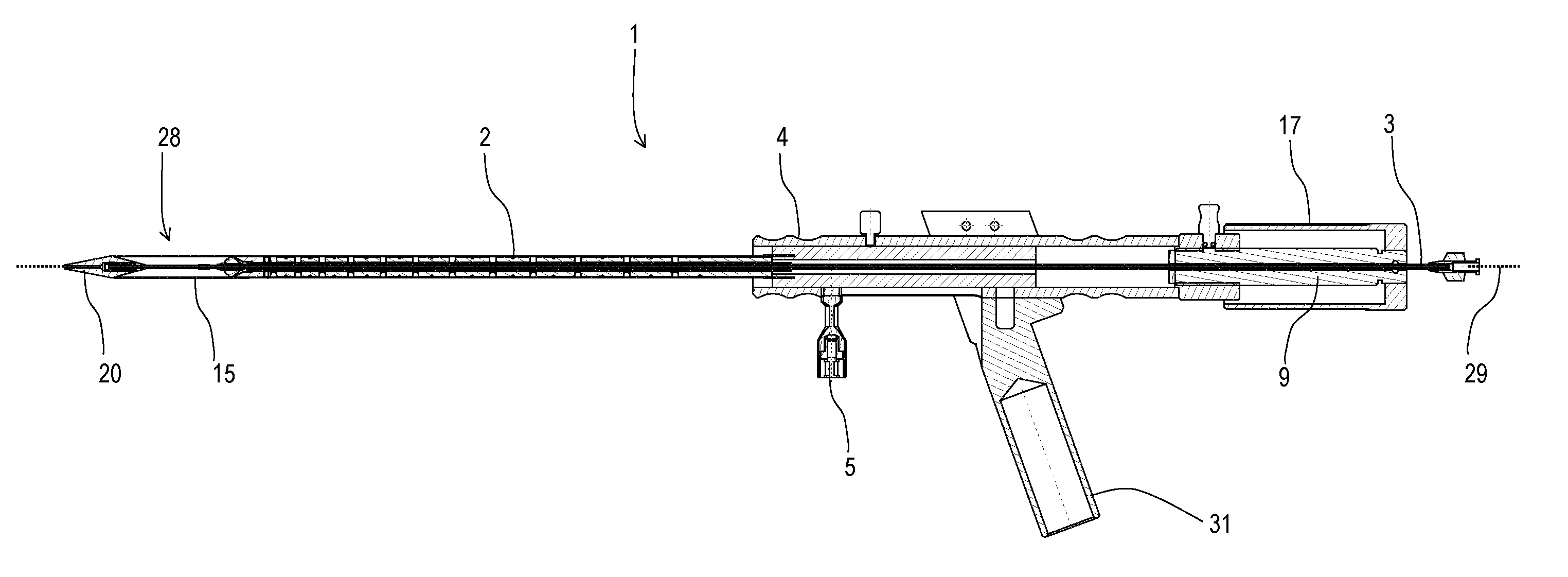
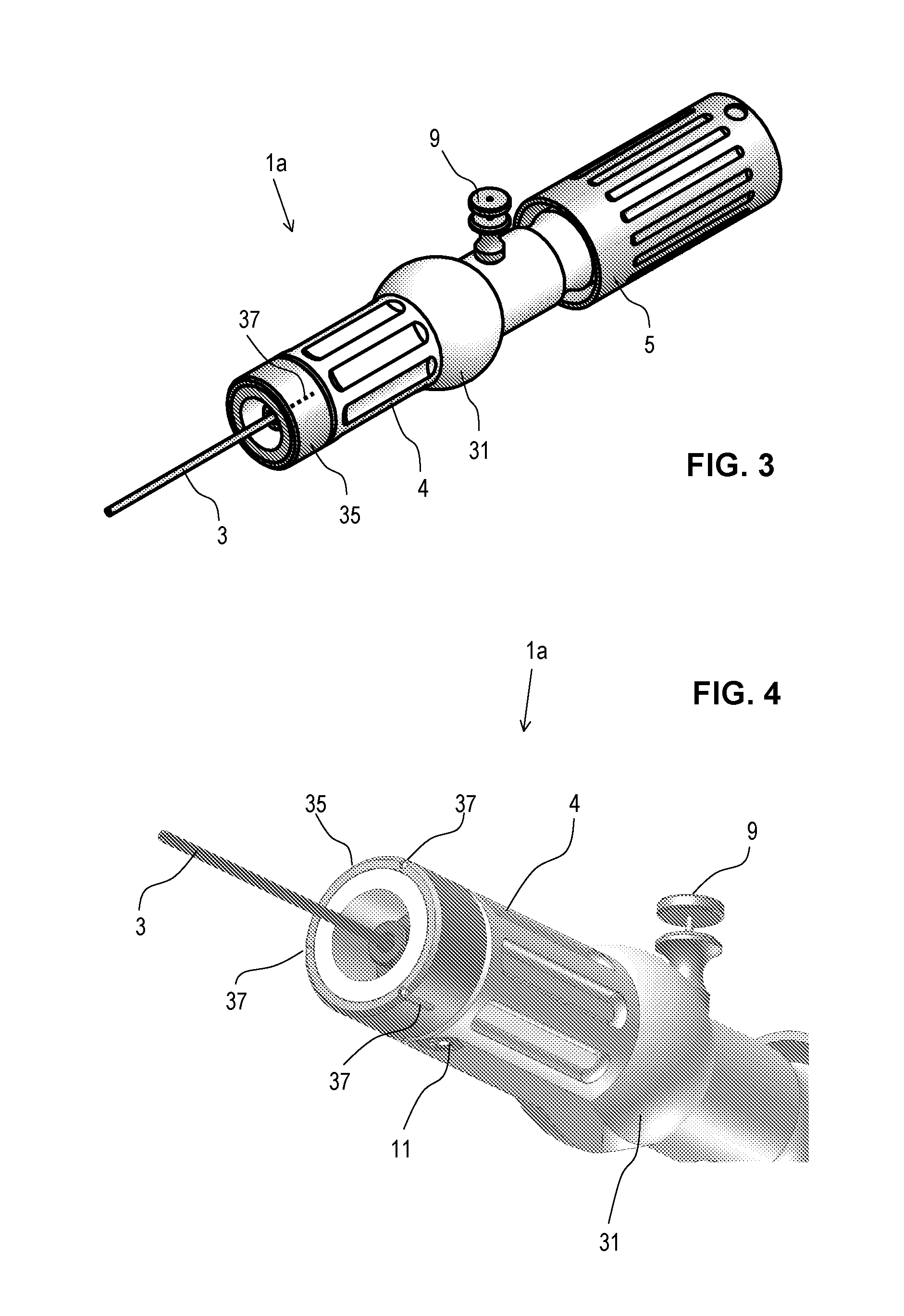
[0121]FIGS. 1-14 illustrate delivery catheter (also referred to as exemplary delivery device 1) for implanting a stent (e.g., valve stent or stent-valve) 15. The delivery catheter 1 comprises a proximal portion 1a to be held by an operator, a distal portion 1b for insertion into the body, and a stem or barrel portion 1c extending between the proximal and distal portions.

[0122]A sheath 2 may extend from the proximal portion 1a to the distal portion 1b where it may cover at least partly a stent 15 accommodated at a stent receiving portion 30, and arranged on tube member 3. Tube member 3 may further comprise a lumen adapted for the insertion of a guide wire 29. The tube member 3 may extend through a handle 4 at the proximal portion 1a. The handle 4 may comprise an actuator for controlling and / or driving linear translation of the sheath 2 in the proximal and / or distal direction(s). Translation of the sheath in e.g., the proximal direction may uncover the stent to deploy or allow deploym...

embodiment 1

[0151]FIG. 15 shows an alternative embodiment 1 of the catheter delivery device 1 according to the present invention. A stent attachment region 28 is located at the distal end of the catheter device, holding the catheter 15. At its most distal tip, the conical section 14 is arranged. The sheath 2 extends from the handle 4 located at the proximal end of the catheter device 1 to the distal end. As such, the sheath 2 may at least partially or completely circumferentially cover the stent 15. Tube member 3 extends along the entire length of the delivery device 1 and comprises a guide wire 29. In this embodiment, the actuation means are configured as trigger element 5. The handle 4 comprises a pistol grip 31 to enable a safe and easy handling of the catheter device by an operator. The device 1 further comprises braking means 9 configured as cylindrical, optionally self turning, threaded element. The threaded element may be analogous to the threaded element 6 as shown on FIG. 4. Said threa...


PUM


Abstract

A delivery catheter for a stent. The delivery catheter may comprise a distal end and a proximal end. The distal end includes a stent attachment region adapted to receive a stent. The stent may be of the self-expanding type. The catheter further comprises a handle at its proximal end and at least one sheath which may at least partially circumferentially cover said stent such as to retain it in a collapsed configuration. The sheath is coupled at its proximal end to an actuator located on said handle portion.

Description

FIELD OF THE INVENTION[0001]The present invention relates to catheter delivery systems for stent valves according to the independent claims.BACKGROUND TO THE INVENTION[0002]Conventional approaches for cardiac valve replacement require the cutting of a relatively large opening in the patient's sternum (“sternotomy”) or thoracic cavity (“thoracotomy”) in order to allow the surgeon to access the patient's heart. Additionally, these approaches require arrest of the patient's heart and a cardiopulmonary bypass (i.e., use of a heart-lung bypass machine to oxygenate and circulate the patient's blood). In recent years, efforts have been made to establish a less invasive transcatheter cardiac valve replacement procedure, via either a transvascular approach, i.e. delivering the new valve through the femoral artery, or by transapical route, where the replacement valve is delivered between ribs and directly through the wall of the heart to the implantation site.[0003]Valve stents for use within...

Claims


Application Information

Patent Timeline
Patent Type & Authority Applications(United States)
IPC IPC(8): A61F2/962A61F2/95
CPCA61F2/2418A61F2/2436A61F2/962A61F2250/0097A61F2002/9517A61F2/9517A61B90/08A61B2090/0811
Inventor ESSINGER, JACQUESDELALOYE, STEPHANEHEFTI, JEAN-LUCMANTANUS, LUC
Owner BOSTON SCI LTD
Why Eureka
Try Eureka