Reach adjustable steering column assembly

a technology of steering column and assembly, which is applied in the direction of steering parts, vehicle components, transportation and packaging, etc., can solve the problems of reducing the energy absorption capacity of the steering column, the collapse of the steering shaft and the shroud, and the design of a suitable energy absorption mechanism for the reach adjustment steering column is quite complex

Active Publication Date: 2021-04-20
TRW LIMITED
View PDF8 Cites 0 Cited by
  • Summary
  • Abstract
  • Description
  • Claims
  • Application Information

AI Technical Summary

Benefits of technology

[0013]an energy absorbing mechanism that acts between the upper shroud part and the second locking part and is configured so that during a crash whereby the upper shroud portion moves telescopically relative to the lower shroud part with the clamp assembly in the clamped position a deformable part of the energy absorbing mechanism is plastically deformed by a deforming part, thereby controlling the movement of the upper shroud portion,
[0015]The invention provides an arrangement in which, during reach adjustment, the two parts of the energy absorbing mechanism move together with the upper shaft and with the second locking part, becoming fixed when the assembly is clamped. This allows an assembly to be provided in which the energy absorbing mechanism functions identically for all reach in and reach out positions, giving predictable control of the collapse during a crash. It also allows for a reduction in parts as the energy absorption mechanism and the second locking part can be combined.
[0016]The second locking part may be fusibly attached to the upper shroud part, through welding or otherwise. The second locking part may be fixed in position relative to the upper shroud part during normal use by the energy absorbing mechanism. This may be the sole fixing of the second locking part to the upper shroud part. The second locking part may also, or alternatively, be fixed to the upper shroud part by a frangible connector which prevents the energy absorbing mechanism being accidentally activated during reach adjustment but breaks in the event of a crash to allow relative movement between the upper shroud part and the second locking part whereby the energy absorbing mechanism can be activated.
[0037]An anti-abuse mechanism may be provided for preventing engagement of the energy absorbing mechanism when the clamping mechanism is in an unclamped position. The anti-abuse mechanism may comprise a rocker arm that pivots around a pivot point having a first arm that extends in one direction from the pivot and engages the first locking part and a locking finger that extends in another direction away from the pivot and moves up and down in opposition to the movement of the first locking part such that when the first locking part is raised the finger is lowered and when the first locking part is lowered the finger is lifted.

Problems solved by technology

This will tend to cause the steering shaft and shroud to collapse.
The design of a suitable energy absorption mechanism for a reach adjustment steering column is quite complex, as it must perform satisfactorily over a range of different reach in and reach out positions of the steering wheel.

Method used


Image

  • Reach adjustable steering column assembly
  • Reach adjustable steering column assembly
  • Reach adjustable steering column assembly

Examples


Embodiment Construction

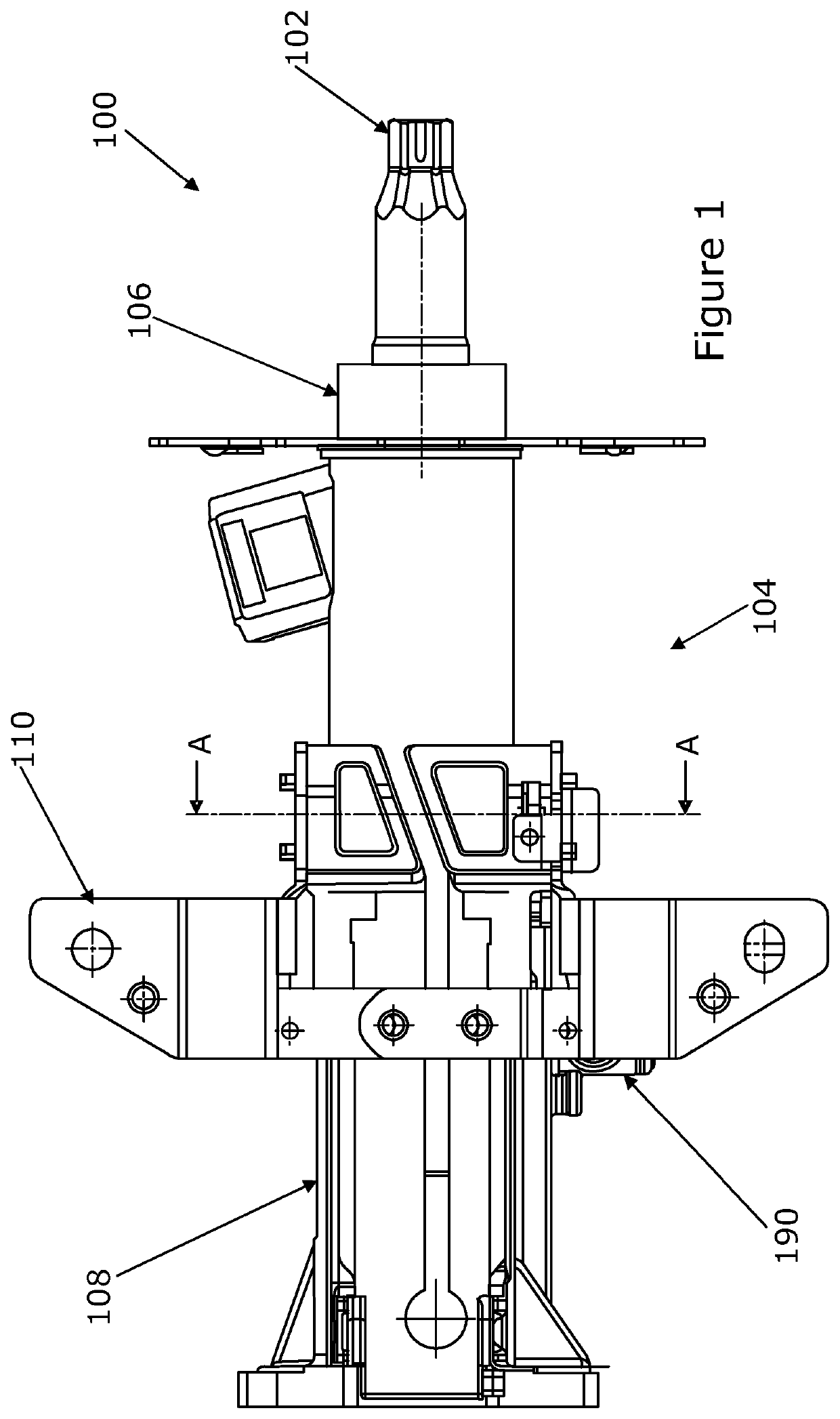
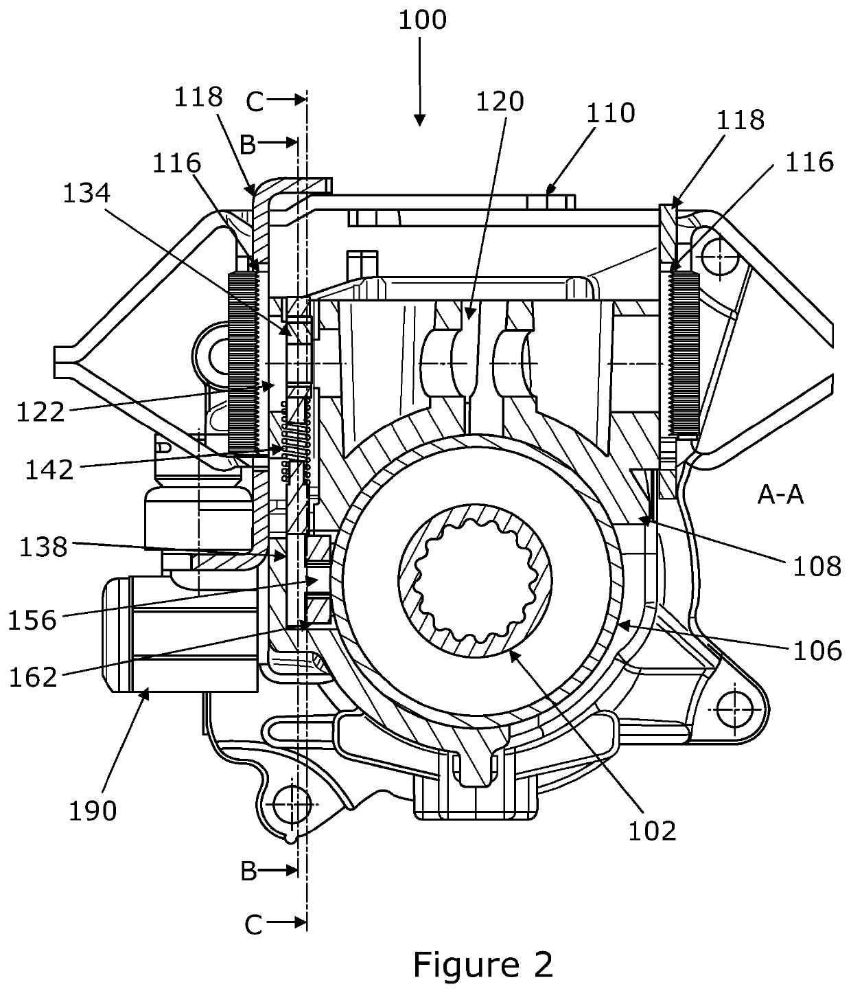
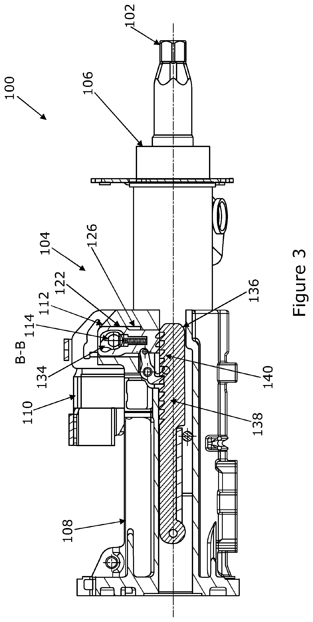
[0053]FIG. 10 shows in perspective an embodiment of a steering column assembly 100 in accordance with the present invention. FIGS. 1 and 2 show the reach adjustable steering column assembly 100 viewed from directly above and in cross section along the line A-A in FIG. 1. FIG. 2 onwards show the assembly 100 from one side along section lines B-B or C-C taken from FIG. 2.

[0054]The assembly 100 comprises a telescopic steering shaft having an upper part 102 and a lower part (not shown), the upper part 102 supporting a steering wheel (not shown) of the vehicle. A two part telescopic shroud 104 supports the steering shaft. The shroud comprises an upper shroud part 106 and a lower shroud part 108, the upper shroud part 106 moving telescopically relative to the lower shroud part 108 during reach adjustment of the steering column assembly 100. FIG. 11 shows the upper shroud part 106 in perspective isolated from the lower shroud part 108 for clarity.

[0055]The shroud 104 is fixed to a gearbox ...


PUM


Abstract

A reach adjustable steering column assembly comprises a telescopic steering shaft which in use supports a steering wheel of the vehicle; a shroud that supports the steering shaft comprising an upper shroud part and a lower shroud part, the upper shroud part moving telescopically relative to the lower part during reach adjustment of the steering column assembly, a support bracket that supports the shroud relative to the vehicle body, and a clamp mechanism that is operable between an unclamped position in which the steering column assembly is adjustable for reach and a clamped position in which the reach position of the steering column assembly is fixed. The clamp mechanism comprises a first locking part that is displaceable by an actuator assembly into and out of positive engagement with a second locking part. An energy absorbing mechanism acts between the upper shroud part and the second locking part and is configured so that during a crash a deformable part of the energy absorbing mechanism is plastically deformed by a deforming part, thereby controlling the movement of the upper shroud part, and in that one of the deformable element and the deforming portion of the energy absorbing mechanism is secured to the upper shroud part, and the other is fixed relative to the second locking part.

Description

CROSS-REFERENCE TO RELATED APPLICATIONS[0001]This application is a national stage of International. Application No. PCT / GB2017 / 053084, filed 12 Oct. 2017, the disclosures of which are incorporated herein by reference in entirety, and which claimed priority to Great Britain Patent Application. No. 1617337.9, filed 12 Oct. 2016, the disclosures of which are incorporated herein by reference in entirety.BACKGROUND TO THE INVENTION[0002]This invention relates to improvements in reach adjustable steering column assemblies for vehicles.[0003]A typical steering column assembly for a vehicle comprises a steering shaft that connects to a steering wheel at one end and a steering gear at the other. Rotation of the steering gear rotates the steering shaft, which in turn operates the steering gear to turn the road wheels of the vehicle. The steering gear may comprise rack and pinion gearbox which converts the rotation of the steering shaft into a reciprocating motion of the steering rack. The ste...

Claims


Application Information

Patent Timeline
Patent Type & Authority Patents(United States)
IPC IPC(8): B62D1/185B62D1/184B62D1/19
CPCB62D1/185B62D1/184B62D1/192B62D1/195
Inventor DAVIES, NICLASKRIVAN, MILOS
Owner TRW LIMITED
Why Eureka
Try Eureka