A fitting method for calculating the main coefficients of the boundary conditions of a groove wall

A technology of boundary conditions and coefficients, applied in computing, computer-aided design, electrical and digital data processing, etc., can solve the problems of inability to realize boundary layer numerical simulation, difficult mathematical modeling, and low accuracy, and achieve high accuracy, Strong practicability and improved accuracy

Active Publication Date: 2018-12-18
INST OF HIGH SPEED AERODYNAMICS OF CHINA AERODYNAMICS RES & DEV CENT +1
View PDF2 Cites 8 Cited by
  • Summary
  • Abstract
  • Description
  • Claims
  • Application Information

AI Technical Summary

Problems solved by technology

[0003] However, the slotted walls induce a through-slot flow between the resident chamber and the test section, which differentiates the wall boundary conditions from the no-penetration, pressure-equilibrium conditions of low-velocity solid walls or open boundaries, except for the two simple conditions In addition to the linear combination, due to the boundary layer shear effect of the grooved surface, a higher order term of the normal perturbation velocity
At present, in engineering applications, the ideal uniform boundary condition of the groove wall based on the assumptions of ideality, irrotation, and small disturbance is mostly used, ignoring the influence of the high-order normal velocity term due to the viscosity of the flow through the groove. The main coefficients in the boundary condition The value is obtained by the empirical method or the comparison method of large and small model force measurement experiments, which has the disadvantages of high cost, long cycle and low accuracy
[0004] In essence, the boundary condition of the groove wall describes the relationship between the pressure difference flowing through the groove and the local airflow deflection angle (and its gradient). This relationship depends on the structure of the groove wall and the flow direction inside the groove, etc., making mathematical modeling difficult ; At the same time, the complex slot structure and the suction effect on the boundary layer make the numerical simulation impossible in the short term. Therefore, the accurate flow characteristics of the slot must be obtained through experimental testing methods
However, the current experimental test is only used to analyze the influence of slotting on the uniformity of the flow field and wave dissipation characteristics, and there is still a lack of methods to obtain accurate boundary conditions of the slot wall using experimental data

Method used


Image

  • A fitting method for calculating the main coefficients of the boundary conditions of a groove wall
  • A fitting method for calculating the main coefficients of the boundary conditions of a groove wall
  • A fitting method for calculating the main coefficients of the boundary conditions of a groove wall

Examples


Embodiment 1

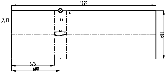
[0056] The fitting method of the present invention is used to calculate the value of the main coefficient of the boundary condition of the groove wall of the 0.6-meter transonic wind tunnel. The test model is a binary airfoil model, the distance between the center of the airfoil and the entrance of the test section is 600mm, the origin is located at the center of the airfoil on the upper wall surface, the X-axis is along the flow direction, the Y-axis is perpendicular to the X-axis, and points in the center plane of the slot Inside the test section, the Z axis is given according to the right-hand rule. Coordinate system definition and main dimensions such as figure 1 shown.

[0057] In this embodiment, the flow direction position is dimensionless by using the chord length of the airfoil, the calculation state is that the incoming flow Mach number M=0.60, and the airfoil model attack angle α=0°. The fitting calculation includes four main steps: smoothing of test data, deducti...


PUM


Abstract

The invention discloses a fitting method for calculating the main coefficients of the boundary conditions of a groove wall based on experimental data, aiming at solving the present situation of lacking accurate calculation of the transonic wind tunnel slot wall boundary condition coefficients. In this method, the least square solution of the overdetermined equations is obtained by fitting the experimental data of the pressure coefficient near the wall and the deflection angle along the flow direction, which exclude the bad points, and the number of the main systems in the boundary condition ofthe wall is obtained by the least square method. The invention needs to eliminate the bad points of the original data, and then subtracts the reference data of the empty wind tunnel from the pressurecoefficient to eliminate the local fluctuation caused by slotting; based on the pressure coefficient-deflection angle nonlinear correlation,an overdetermined equation is established, the least squaresolution of the overdetermined equations is obtained by using the pseudo-inverse of the coefficient matrix, and the number of coefficients of the gradient term, the first order term and the second order term of the deflection angle in the boundary condition of the channel wall is obtained. The invention can improve the accuracy of the boundary conditions of the groove wall and guide the aerodynamic design and correction of the groove wall.

Description

technical field [0001] The invention relates to the field of experimental aerodynamics, in particular to a fitting method for calculating the main coefficients of the boundary conditions of tank walls. The present invention is essentially a fitting method for calculating the coefficients of the boundary conditions of the tank wall, which is based on experimental data and used for calculating the main coefficients of the fitted tank wall boundary conditions, and has high application value. Background technique [0002] In the transonic wind tunnel, in order to avoid clogging during operation and reduce the clogging effect in the subsonic range, the wall plates of the test section are in the form of openings or slots. In the high subsonic range, compared with the hole wall, the groove wall has the characteristics of less interference, low noise, and convenient processing and adjustment, making it gradually become the development trend of transonic wind tunnels. At present, ad...

Claims


Application Information

Patent Timeline
Patent Type & Authority Applications(China)
IPC IPC(8): G06F17/50
CPCG06F30/20G06F2119/06
Inventor 刘光远魏志林学东李浩王瑞波杨国超郭秋亭邓吉龙杨昕鹏贾智亮陈学孔
Owner INST OF HIGH SPEED AERODYNAMICS OF CHINA AERODYNAMICS RES & DEV CENT
Why Eureka
Try Eureka