Magnetic attraction connector of lamp
A technology of connector and magnetic attraction, which is applied in the direction of connection, flexible/rotatable wire connector, two-part connection device, etc. It can solve the problems of inconvenient installation, inability to adjust the angle of the lamp body, and inability to rotate arbitrarily, so as to achieve installation and Ease of use
- Summary
- Abstract
- Description
- Claims
- Application Information
AI Technical Summary
Problems solved by technology
Method used
Image

Examples
Embodiment Construction
[0017] The present invention will be described below in conjunction with the accompanying drawings and specific embodiments.
[0018] refer to Figure 1-5 :
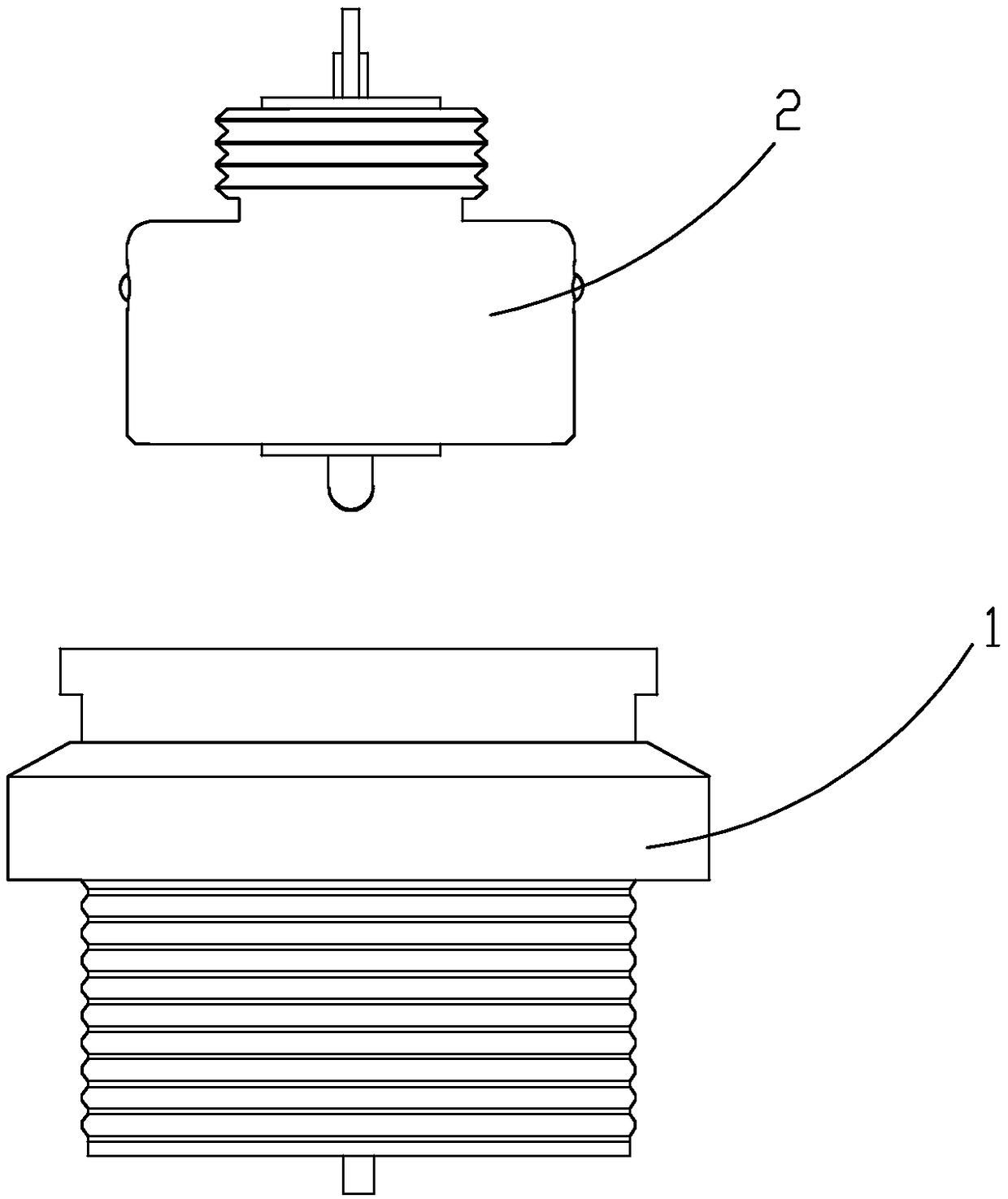
[0019] A magnetic connector for lamps, comprising a magnetic female connector 1 and a magnetic male connector 2 .
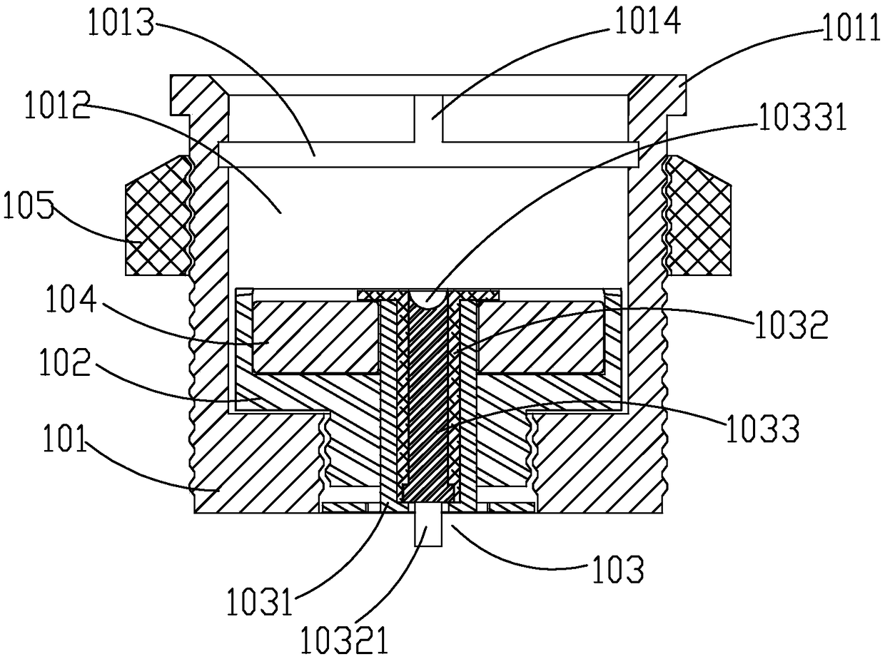
[0020] The magnetic female connector includes a fixed sleeve 101 for fixing on the lamp body, a female connection insulating sleeve 102, a female connection conductive cylinder 103 and a female connection magnet 104, wherein:
[0021] The outer wall of the front part of the fixing sleeve 101 is provided with a rib ring 1011 engaged with the lamp body, and the rear part is screwed with a locking nut 105 for locking it on the lamp body;
[0022] The female connection insulating sleeve 102 is set in the fixed sleeve 101, and its rear end is screwed and fixed in the threaded hole provided at the rear of the fixed sleeve 101 through the external thread provided on the outer wall, so as to be fixedly installed ...
PUM
 Abstract
Description
Claims
Application Information
PatSnap Eureka turns technology decisions into work you can execute. Powered by our Innovation Knowledge Graph, it runs expert workflows across engineering, life sciences, materials and intellectual property. Get your review-ready output in minutes.


