Vehicle-mounted camera with dust removal effect

A camera and function technology, applied in the field of vehicle cameras, can solve problems such as affecting the use of setting head shooting, affecting the quality of law enforcement shooting, freezing of water droplets, etc., so as to ensure the quality of shooting, prevent freezing, and improve accuracy.

Active Publication Date: 2019-03-08
浙江咪网电子科技有限公司
View PDF15 Cites 13 Cited by
  • Summary
  • Abstract
  • Description
  • Claims
  • Application Information

AI Technical Summary

Problems solved by technology

[0003] When the police need to go out to enforce the law, when the existing camera is following the police car to enforce the law, the dust on the mirror surface of the camera will seriously affect the quality of law enforce

Method used


Image

  • Vehicle-mounted camera with dust removal effect
  • Vehicle-mounted camera with dust removal effect
  • Vehicle-mounted camera with dust removal effect

Examples


Embodiment 1

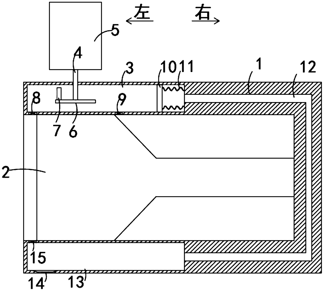
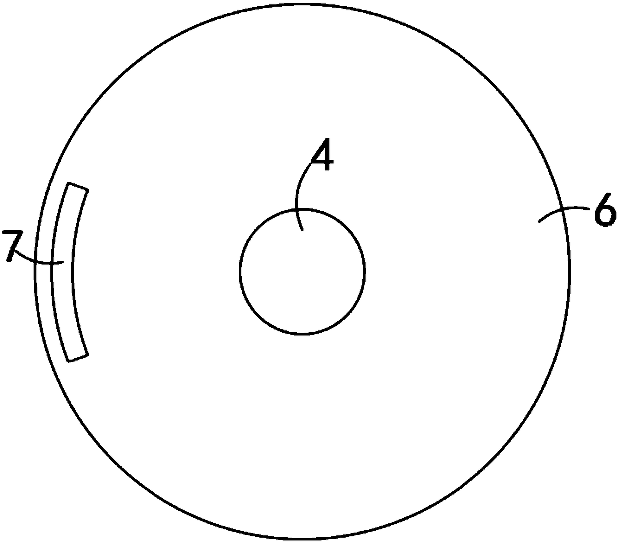
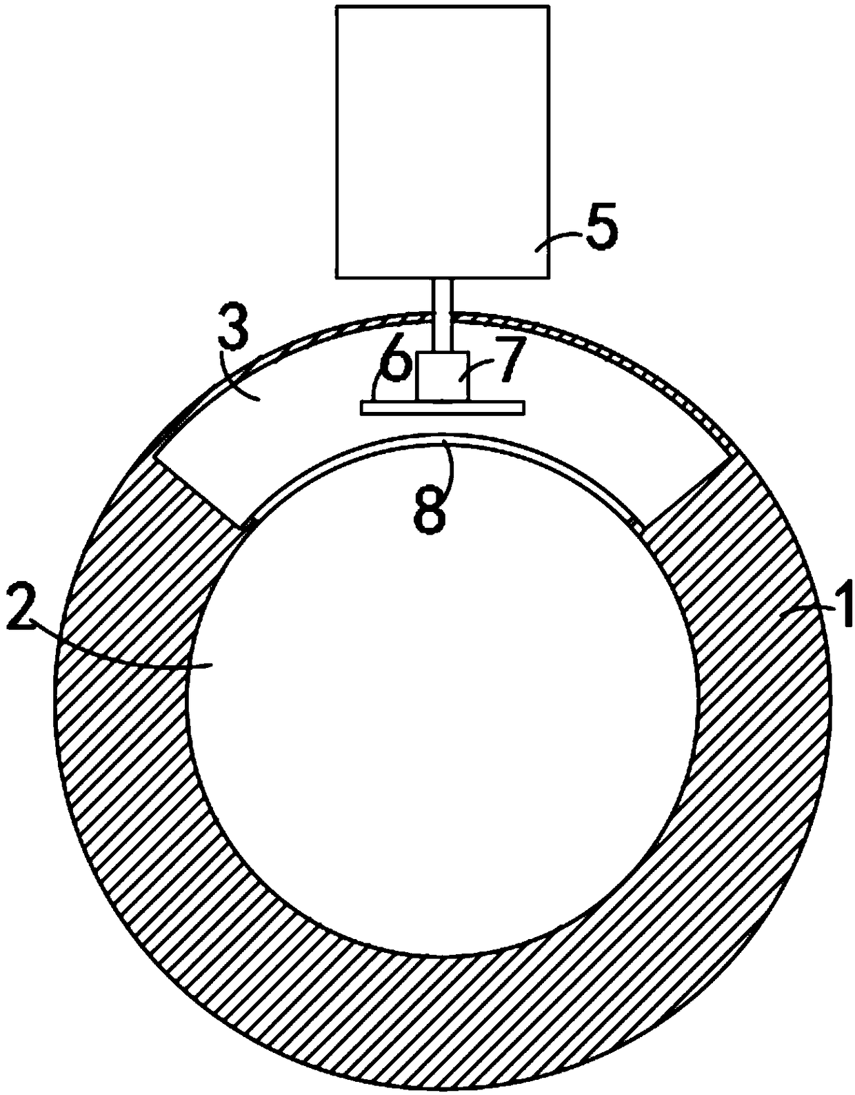
[0021] Such as Figure 1-3 As shown, a vehicle-mounted camera with a dust removal function includes a camera body 1, and a lens 2 is sealed and installed in the camera body 1. It should be noted that the mirror surface of the lens 2 is a plane mirror, and the upper side wall of the camera body 1 is provided with a second A cavity 3, the top surface of the first cavity 3 is provided with a through hole communicating with the inside and outside, and the rotation in the through hole is provided with a rotating rod 4, and a vertical fan 5 is installed on the upper end of the rotating rod 4. It is worth mentioning that, In autumn and winter, when the fog is large, the surface of the lens 2 is prone to frost and ice. The joint between the rotating rod 4 and the first cavity 3 is provided with a sealing ring to ensure the sealing of the first cavity 3. The lower end of the rotating rod 4 is fixed Connected with a disk 6, the upper edge of the disk 6 is fixedly connected with a magnet...

Embodiment 2

[0027] Such as Figure 4-5 As shown, the difference between this embodiment and Embodiment 1 is that: the bottom of the first cavity 3 is fixedly connected with a plurality of telescopic rods 16, and the upper ends of the plurality of telescopic rods 16 are fixed with a friction plate that rubs against the disc 6 and heats up. 18, wherein both the friction plate 18 and the disc 6 are made of metal, and the drive of the external airflow can cause the disc 6 to rotate rapidly, so that the disc 6 and the friction plate 18 rub against each other and generate heat, and the friction is stable and cannot reach the 6 and the melting point of the friction plate 18, the friction plate 18 is a hollow plate, which is convenient for heating the gas in the first cavity 3, and the second spring 17 is set on the telescopic rod 16. It should be noted that the second spring 17 Both ends are fixedly connected with the bottom of the first cavity 3 and the lower end of the friction plate 18 respec...


PUM


Abstract

The invention belongs to the technical field of monitoring camera equipment and in particular relates to a vehicle-mounted camera with a dust removal effect. The vehicle-mounted camera comprises a camera body, a lens is mounted in the camera body in a sealing way, a first cavity is arranged in the side wall of the upper end of the camera body, a through hole communicating inside with outside is formed in the top surface of the first cavity, a rotary rod is arranged in the through hole in rotatable and penetrating ways, a vertical fan is mounted at the upper end of the rotary rod, the lower endof the rotary rod is fixedly connected with a disk, a magnet is fixedly connected with the edge of the upper end of the disk, a dust removal port used for removing dust on the lens is arranged at thebottom of the first cavity, a fourth unidirectional pressure value is mounted in the dust removal port, an air inlet used for pumping hot air in the camera body is formed in the bottom of the first cavity, and a first unidirectional pressure valve is mounted in the air inlet. The vehicle-mounted camera provided by the invention has the advantages that dust removal can be performed on the lens ofthe camera and the phenomenon that water drops on the surface are frozen when the lens is used in winter also can be prevented.

Description

technical field [0001] The invention belongs to the technical field of surveillance camera equipment, and in particular relates to a vehicle-mounted camera with dust removal function. Background technique [0002] Camera, also known as computer camera, computer eye, electronic eye, etc., is a video input device, which is widely used in video conferencing, telemedicine and real-time monitoring. car camera. [0003] When the police need to go out to enforce the law, when the existing camera is following the police car to enforce the law, the dust on the mirror surface of the camera will seriously affect the quality of law enforcement shooting and the result of law enforcement judgment. In foggy weather, the water droplets on the mirror surface are prone to freezing due to the influence of the weather, which seriously affects the shooting and use of the setting head. [0004] For this reason, we propose a vehicle camera with dust removal function to solve the above problems. ...

Claims


Application Information

Patent Timeline
IPC IPC(8): H04N5/225G03B17/55B60S1/56G03B30/00
CPCG03B17/55B60S1/56H04N23/50
Inventor 杨志刚
Owner 浙江咪网电子科技有限公司
Why Eureka
Try Eureka