a sand conveyor line

A conveyor line, sand technology, applied in the direction of conveyors, transportation and packaging, loading/unloading, etc., can solve problems such as obstruction

Active Publication Date: 2020-09-11
ZHEJIANG BOYU ELECTROMECHANICAL
View PDF6 Cites 0 Cited by
  • Summary
  • Abstract
  • Description
  • Claims
  • Application Information

AI Technical Summary

Problems solved by technology

But because the direction of movement of the chain bucket 10d on the A side is opposite to the direction in which the sand enters the lower casing 10a, it hinders the sand from entering the lower casing 10a to a certain extent.

Method used


Image

  • a sand conveyor line
  • a sand conveyor line
  • a sand conveyor line

Examples


Embodiment Construction

[0030] The above and other technical features and advantages of the present invention will be clearly and completely described below in conjunction with the accompanying drawings. Apparently, the described embodiments are only some of the embodiments of the present invention, not all of them.

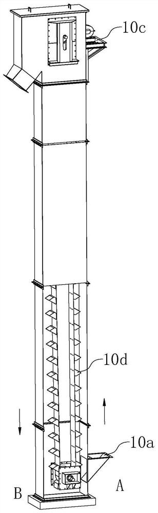
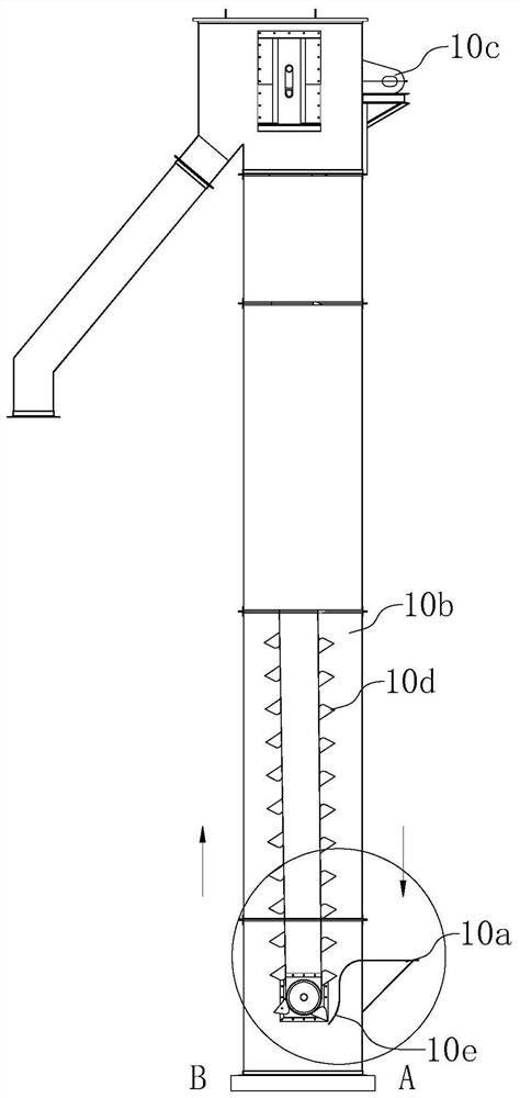
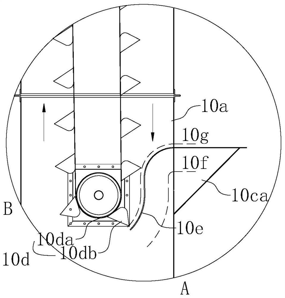
[0031] In one embodiment, such as figure 2 and image 3 shown. The chain bucket elevator provided in this embodiment, such as figure 2 shown. It includes an upper casing 10c, an intermediate casing 10b, and a lower casing 10a connected in sequence from top to bottom, and also includes a chain bucket 10d and The S-shaped partition 10e arranged in the lower casing 10a. Such as image 3 As shown, the S-shaped partition 10e is vertically arranged at the feed inlet 10ca of the lower casing 10a, and the S-shaped partition 10e separates the lower end of the feed inlet 10ca and the chain bucket 10d; one part of the S-shaped partition 10e The side and the feed port 10ca form a downward f...


PUM


Abstract

The invention provides a chain bucket elevator for engineering and a sand conveying line. The chain bucket elevator for engineering comprises an upper casing pipe, a middle casing pipe and a lower casing pipe which are connected sequentially from top to bottom and further comprises a chain bucket arranged inside the upper casing pipe, the middle casing pipe and the lower casing pipe and an S-shaped separating plate arranged inside the lower casing pipe; the S-shaped separating plate is vertically arranged at a feeding opening of the lower casing pipe and separates the feeding opening fromthe lower end of the chain bucket; one side of the S-shaped separating plate and the feeding opening form a downward feeding channel; the other side of the S-shaped separating plate forms a moving channelallowing the chain bucket to move downwards; one half, facing the feeding opening, of the chain bucket moves downwards; and the other half, opposite to the feeding opening, of the chain bucket moves upwards.

Description

technical field [0001] The invention relates to the technical field of sand transportation, in particular to an engineering chain bucket elevator and a sand transportation line. Background technique [0002] The sand drying system is a drying system that handles a large amount of material. In one of the links of sand transportation, chain bucket elevators are often used. At present, the more common chain bucket elevators on the market such as figure 1 shown. During operation, sand enters from the lower casing 10a and is lifted to the upper casing 10c under the action of the chain bucket 10d. It should be noted that the sand enters the lower casing 10a downward from the A side, and the chain bucket 10d rises upwards on the A side (A and B sides in the figure show the rising and falling directions of the chain bucket 10d respectively with arrows), so that the The sand is lifted to the upper casing 10c. But because the direction of movement of the chain bucket 10d on the A...

Claims


Application Information

Patent Timeline
Patent Type & Authority Patents(China)
IPC IPC(8): B65G17/12B65G21/00B65G69/18B65G69/20
CPCB65G17/126B65G21/00B65G69/188B65G69/20B65G2201/045
Inventor 黄秀媚
Owner ZHEJIANG BOYU ELECTROMECHANICAL
Why Eureka
Try Eureka