Liquid delivery device with blocking clutch

A transmission device, clutch technology, applied in the direction of fluid transmission, transmission, belt/chain/gear, etc., can solve the problems of difficulty in ensuring the durability of sealing elements, increase in the number of parts, increase in cost, etc., to achieve enhanced connection responsiveness, The effect of cost reduction and durability guarantee

Inactive Publication Date: 2005-04-06
YUTAKA GIKEN CO LTD +1
View PDF1 Cites 0 Cited by
  • Summary
  • Abstract
  • Description
  • Claims
  • Application Information

AI Technical Summary

Problems solved by technology

This liquid transmission device has the following problems: it requires a one-way valve to be set in the clutch piston so that when the lock-up clutch is released, the working oil can flow from the outer oil chamber to the inner oil chamber, which inevitably leads to an increase in the number of parts and in turn to an increase in cost; moreover, when the pump impeller and the turbine rotor rotate relative to each other in the unconnected state of the lock-up clutch, the sealing elements on the outer periphery of the clutch piston often scratch the inner periphery of the side cover surface, thus it is difficult to ensure the durability of the sealing element

Method used


Image

  • Liquid delivery device with blocking clutch
  • Liquid delivery device with blocking clutch
  • Liquid delivery device with blocking clutch

Examples


Embodiment Construction

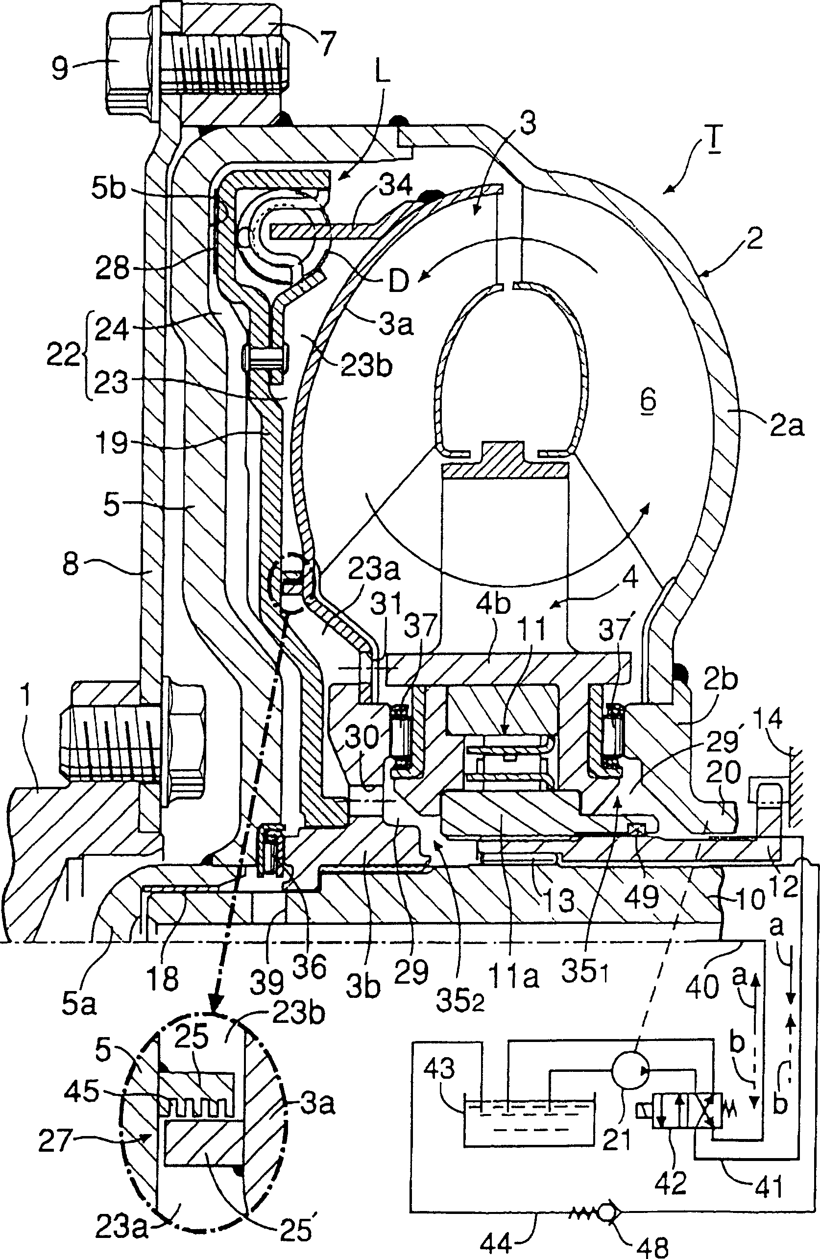
[0019] see figure 1 , the torque converter T as a hydraulic transmission device has a pump impeller 2 , a turbine rotor 3 opposite to the pump impeller 2 , and a stator 4 disposed between the inner periphery of the pump impeller 2 and the turbine rotor 3 . Between the three elements 2 , 3 and 4 is defined a circulation line 6 for transmitting power by means of working oil.

[0020] The side cover 5 is integrally connected to the casing 2 a of the pump impeller 2 by welding, and is used to cover the outer surface of the turbine rotor 3 . A group of connecting bosses 7 are arranged around and welded to the outer peripheral surface of the side cover 5 . A drive plate 8 matching a crankshaft 1 of an engine is fixed to the connection boss 7 by means of bolts 9 . A thrust needle bearing 36 is inserted between the hub 3 b of the turbine rotor 3 and the side cover 5 .

[0021] The output shaft 10 is disposed at the center of the torque converter T so as to be coaxial with the crank...


PUM


Abstract

A fluid transmitting device includes a side cover connected to a pump impeller and defining a clutch chamber between the side cover and an outer surface of a turbine runner, and a lock-up clutch which includes a clutch piston connected to the turbine runner. The clutch chamber is divided by the clutch piston into an inner oil chamber and an outer oil chamber. In the fluid transmitting device, a dividing means for dividing the inner oil chamber into a primary inner oil chamber section and a secondary inner oil chamber section is provided between the turbine runner and the clutch piston. When a lock-up control device is operated to urge the clutch piston in a clutch switch-on direction, the pressures in the primary inner oil chamber section and the secondary inner oil chamber section are raised in the named order relative to the outer oil chamber. Thus, the connection responsiveness of the lock-up clutch can be enhanced in a simple structure.

Description

technical field [0001] The present invention relates to liquid transfer devices, such as torque converters for use in power transmission systems of vehicles and industrial machines, liquid fittings and the like, and more particularly to liquid transfer devices with lock-up clutches having pump impellers, turbine a rotor, a circulation duct defined between the turbine rotor itself and the pump impeller, a side cover connected to the pump impeller, and a clutch chamber defined between the side cover itself and the outer surface of the turbine rotor so as to communicate with the outer periphery of the circulation duct, And the lock-up clutch, which is arranged in the clutch chamber, and can directly connect the side cover and the turbine rotor with each other; the lock-up clutch has a clutch piston, which is axially movably connected to the turbine rotor, so as to separate the clutch chamber into an inner oil chamber and an outer oil chamber on the side of the side cover, a locko...

Claims


Application Information

Patent Timeline
Patent Type & Authority Patents(China)
IPC IPC(8): F16H61/14F16H45/02
CPCF16H45/02
Inventor 齐藤洁丸山徹郎
Owner YUTAKA GIKEN CO LTD
Why Eureka
Try Eureka