
Eureka
For R&D, Eureka makes reading and utilizing patents & technical documents easy.
Eureka AIR
Designed for self-driven R&D workflows. Generate viable solutions, solve complex R&D challenges, empower your innovation with AI.

Eureka Materials
Designed for material experts only. Revolutionize your material R&D, from search, analyze, to developing new materials.

TechResearch
Generate reliable direction feasibility study reports for your R&D in just a few steps.

TechSeek
Discover and master advanced knowledge NOW. Basics, ideas, possibilities, all at once.

TechMind
As an expert in R&D Theories, TechMind can generates customized viable solutions instantly.

TechRisk
Analyze your overall solution with one click, know your potential R&D risks in advance.

TechMonitor
Get weekly tech updates, stay abreast of the latest tech innovations and key insights.
Anomaly detection system of passenger conveyer
A passenger conveyor, anomaly detection technology, applied in transportation and packaging, escalators, etc., can solve passenger troubles and other problems
- Summary
- Abstract
- Description
- Claims
- Application Information
AI Technical Summary
Problems solved by technology
Method used
Image

Examples
no. 1 approach
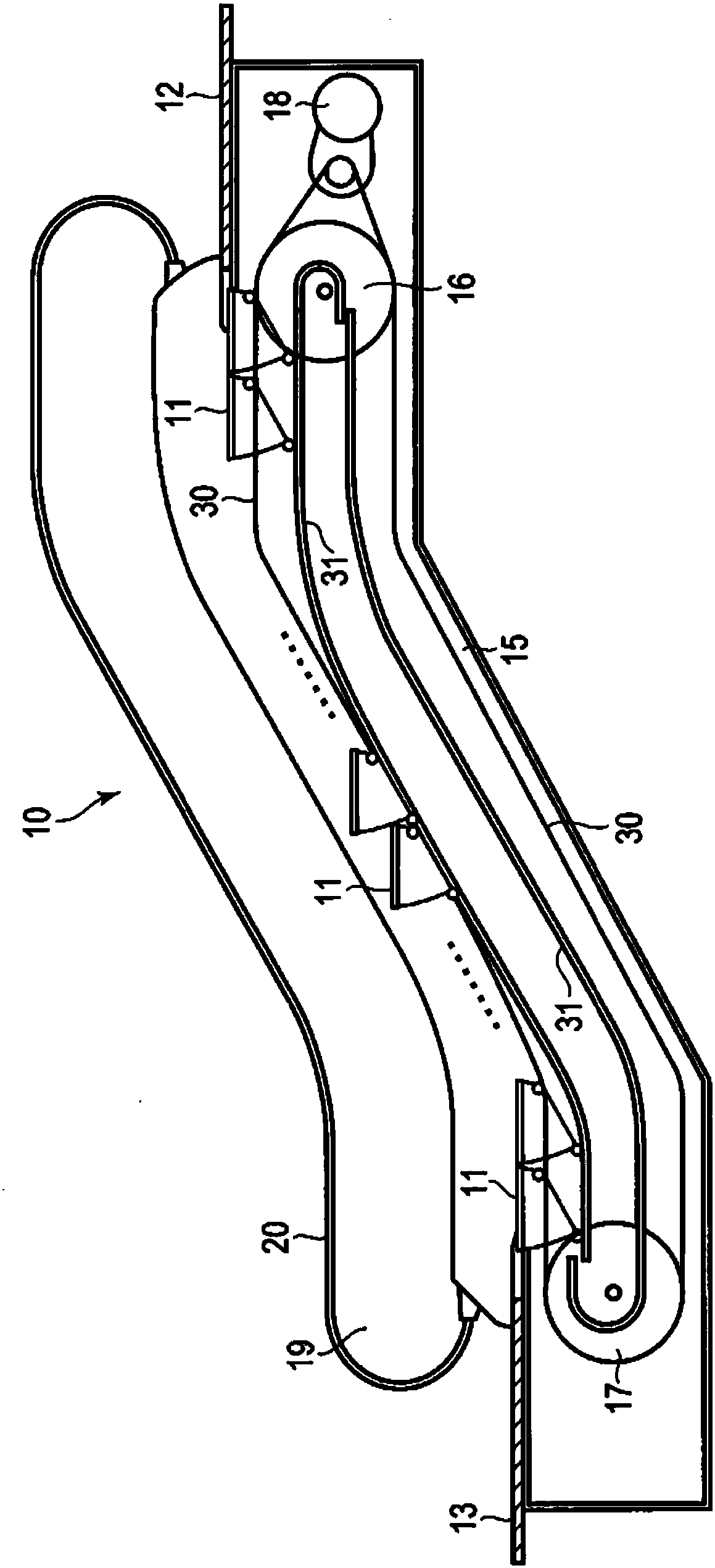
[0054] figure 1 It is a figure which shows the overall schematic structure of the escalator in 1st Embodiment. 10 in the figure represents the whole escalator.
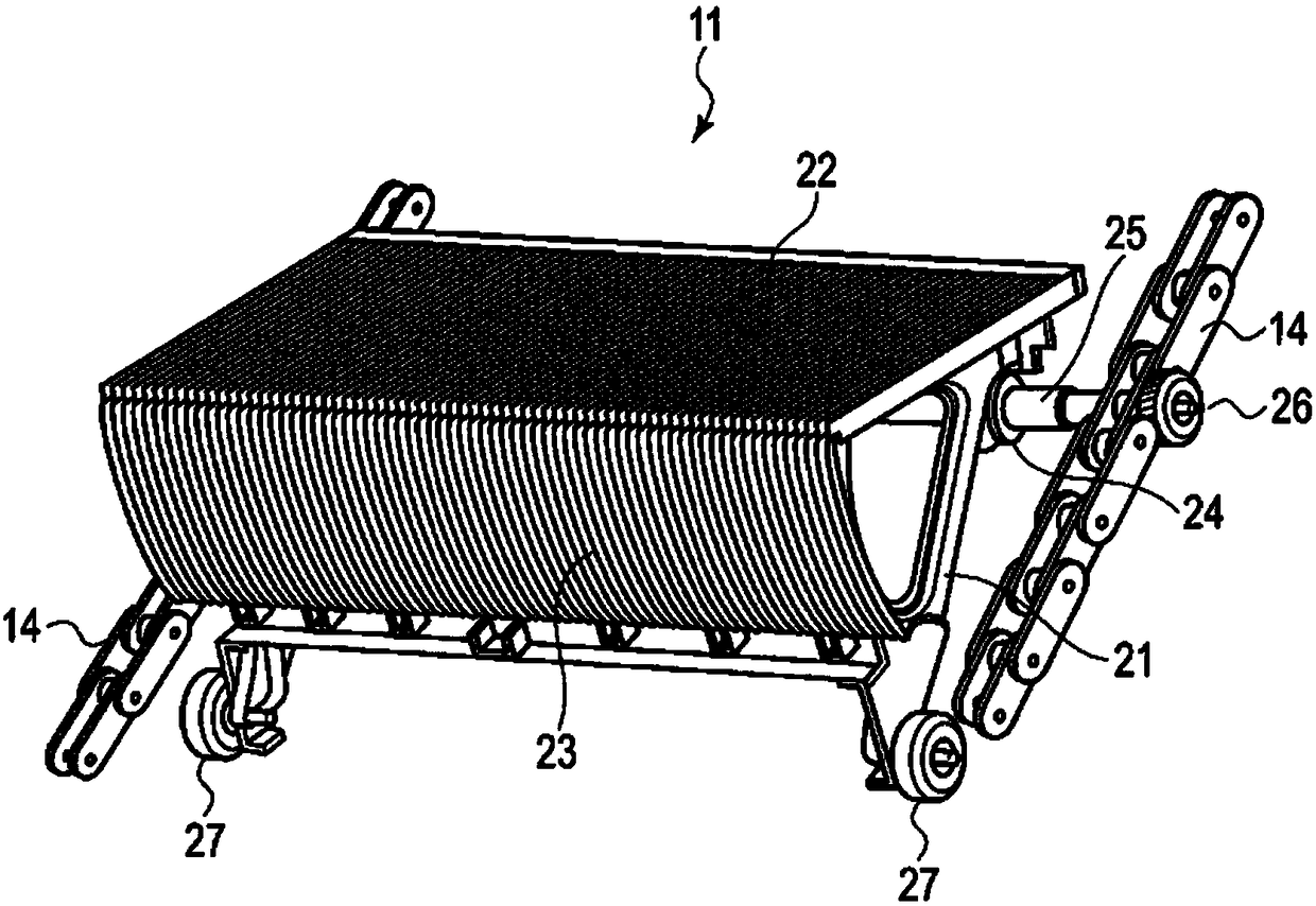
[0055] The escalator 10 is, for example, installed obliquely between the upper and lower floors of a building, and circulates a plurality of steps (steps) 11 between the landing of the upper machine room 12 and the landing of the lower machine room 13 . Each rung 11 utilizes figure 2 The illustrated endless link chains 14 are connected to each other and arranged in a truss 15 installed under the floor of the building. Inside the truss 15, an upper sprocket 16 and a lower sprocket 17 are arranged, and a connecting chain 14 is wound between them.
[0056] A driving device 18 having a motor, a speed reducer, or the like is coupled to either one of the upper sprocket 16 and the lower sprocket 17 (in this example, the upper sprocket 16 ). Driven by the driving device 18, the sprockets 16 and 17 rotate, and the plurali...
no. 2 approach
[0110] Next, a second embodiment will be described.
[0111] The above-mentioned first embodiment is a mirror system in which two optical axes are formed using a reflector, whereas the second embodiment is a mirrorless system in which two optical axes are formed without using a reflector.
[0112] Figure 16 It is a figure which shows the structure of the abnormality detection system of a mirrorless system in 2nd Embodiment.
[0113] On the circuit side of the escalator 10, the left wheel 27a and the right wheel 27b of the step 11 are supported by a pair of guide rails 31a, 31b provided on both sides of the step 11, and move from left to right. The difference from the above-mentioned first embodiment is that there is no reflector 53 as a reflector, and instead, two sets of transmissive photoelectric sensors 70a, 70b are used to form two optical axes 73a, 70b on the travel paths of the wheels 27a, 27b. 73b.
[0114] The first transmissive photoelectric sensor 70a is separate...
no. 3 approach
[0135] Next, a third embodiment will be described.
[0136] The third embodiment is a configuration in which two optical axes cross each other in a mirrorless abnormality detection system.
[0137] Figure 19 It is a figure which shows the structure of the abnormality detection system of a mirrorless system in 3rd Embodiment. In addition, the same code|symbol is attached|subjected to the same part as said 2nd Embodiment, and it demonstrates.
[0138] There is a configuration in which the passage of the left wheel 27a and the right wheel 27b of the step 11 is detected at two positions using two sets of transmissive photoelectric sensors 70a and 70b. The difference from the above-mentioned second embodiment is that the optical axis 73a of the first transmissive photoelectric sensor 70a intersects with the optical axis 73b of the second transmissive photoelectric sensor 70b.
[0139] That is, the light projection part 71a and the light projection part 71b are spaced apart by a...
PUM
 Abstract
Description
Claims
Application Information
 - R&D Engineer
- R&D Manager
- IP Professional
- Industry Leading Data Capabilities
- Powerful AI technology
- Patent DNA Extraction
Browse by: Latest US Patents, China's latest patents, Technical Efficacy Thesaurus, Application Domain, Technology Topic, Popular Technical Reports.
© 2024 PatSnap. All rights reserved.Legal|Privacy policy|Modern Slavery Act Transparency Statement|Sitemap|About US| Contact US: help@patsnap.com