Sensor failure or abnormality detecting system incorporated in a physical or dynamic quantity detecting apparatus

a technology of abnormality detection and detecting system, which is applied in the direction of safeguarding apparatus, instruments, force measurement, etc., can solve the problems of bridge circuit producing an erroneous voltage difference, sensor producing an erroneous electric signal, and pressure sensor not desirabl

Inactive Publication Date: 2002-07-23
DENSO CORP
View PDF23 Cites 140 Cited by
  • Summary
  • Abstract
  • Description
  • Claims
  • Application Information

AI Technical Summary

Benefits of technology

Furthermore, providing at least six gauge resistors electrically connected to each other makes it possible to select two connecting points whose voltage levels do not vary in response to an applied pressure as far as all of the gauge registers are normal. The two selected connecting points are other than the two connecting points used for detecting the applied pressure.
If any failure occurs in a gauge resistor during the operation of the sensor, the voltage difference between two selected connecting points causes a variation and can be detected as a failure of the sensor. Accordingly, it becomes possible to provide a pressure sensor capable of detecting an abnormality in its output sensitivity.

Problems solved by technology

However, the bridge circuit produces an erroneous voltage difference when spoiled or wounded.
In such a case, the pressure sensor produces an erroneous electric signal.
However, this pressure sensor is not desirable in that the area of pressure sensing portion is doubled due to separation of the diaphragm portion along the center line.
Thus, downsizing of the pressure sensor is difficult.
This makes it difficult to detect a sensor failure by solely monitoring the sensor output.
However, when the same pressure is detected as two series of signals like the above-described failure detecting method, a similar situation possibly appear when these signals are compared mutually.
Hence, it is impossible to accurately detect the sensor failure.

Method used


Image

  • Sensor failure or abnormality detecting system incorporated in a physical or dynamic quantity detecting apparatus
  • Sensor failure or abnormality detecting system incorporated in a physical or dynamic quantity detecting apparatus
  • Sensor failure or abnormality detecting system incorporated in a physical or dynamic quantity detecting apparatus

Examples


seventh embodiment

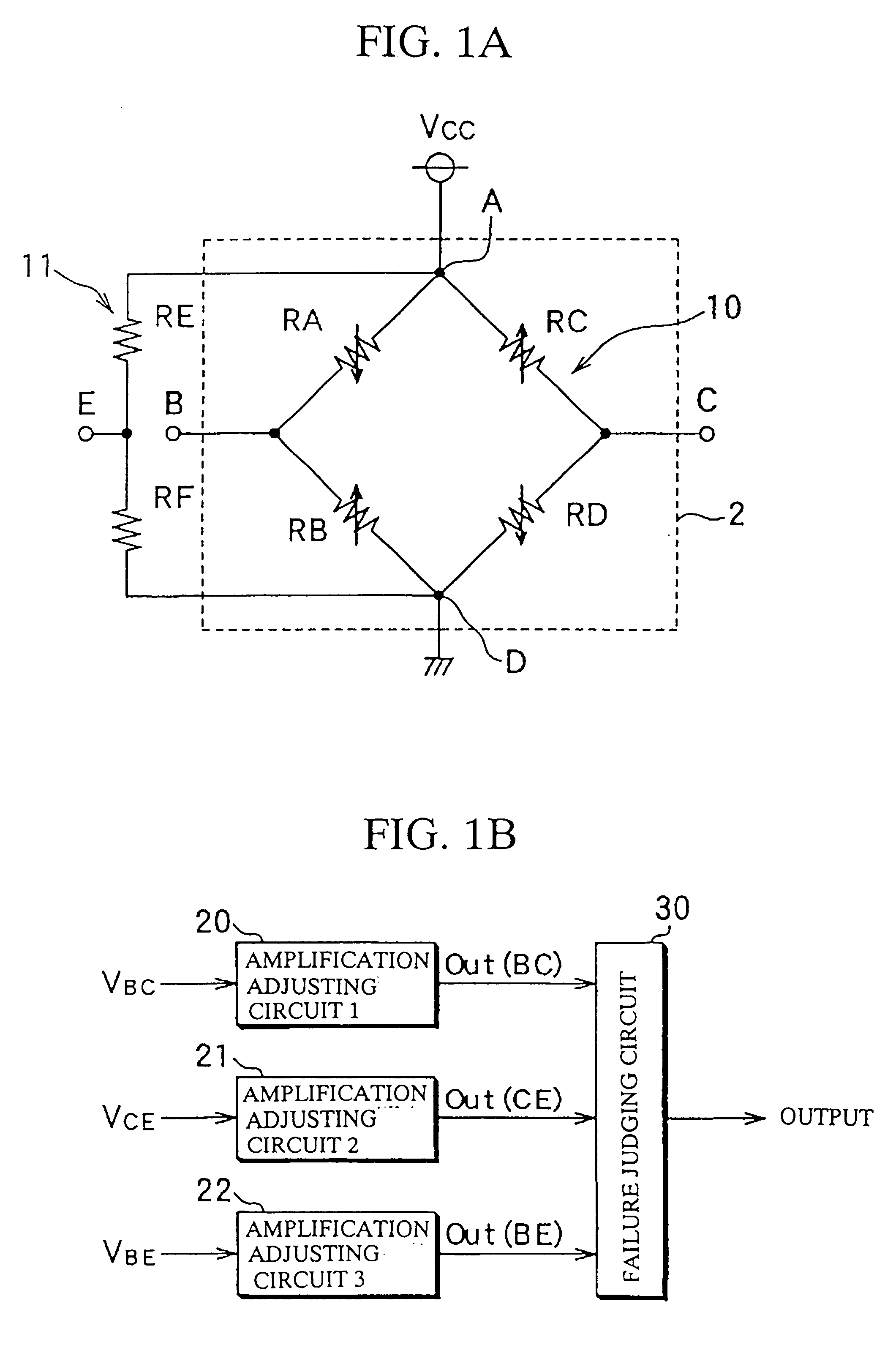
A seventh embodiment of the present invention will be explained with reference to FIGS. 13A and 13B. A pressure sensor of the seventh embodiment differs from the pressure sensor of the sixth embodiment in that the failure detecting bridge circuit 14 is formed by four thin-film resistors. The components similar to those disclosed in the sixth embodiment are denoted by the same reference numerals and will not be explained.

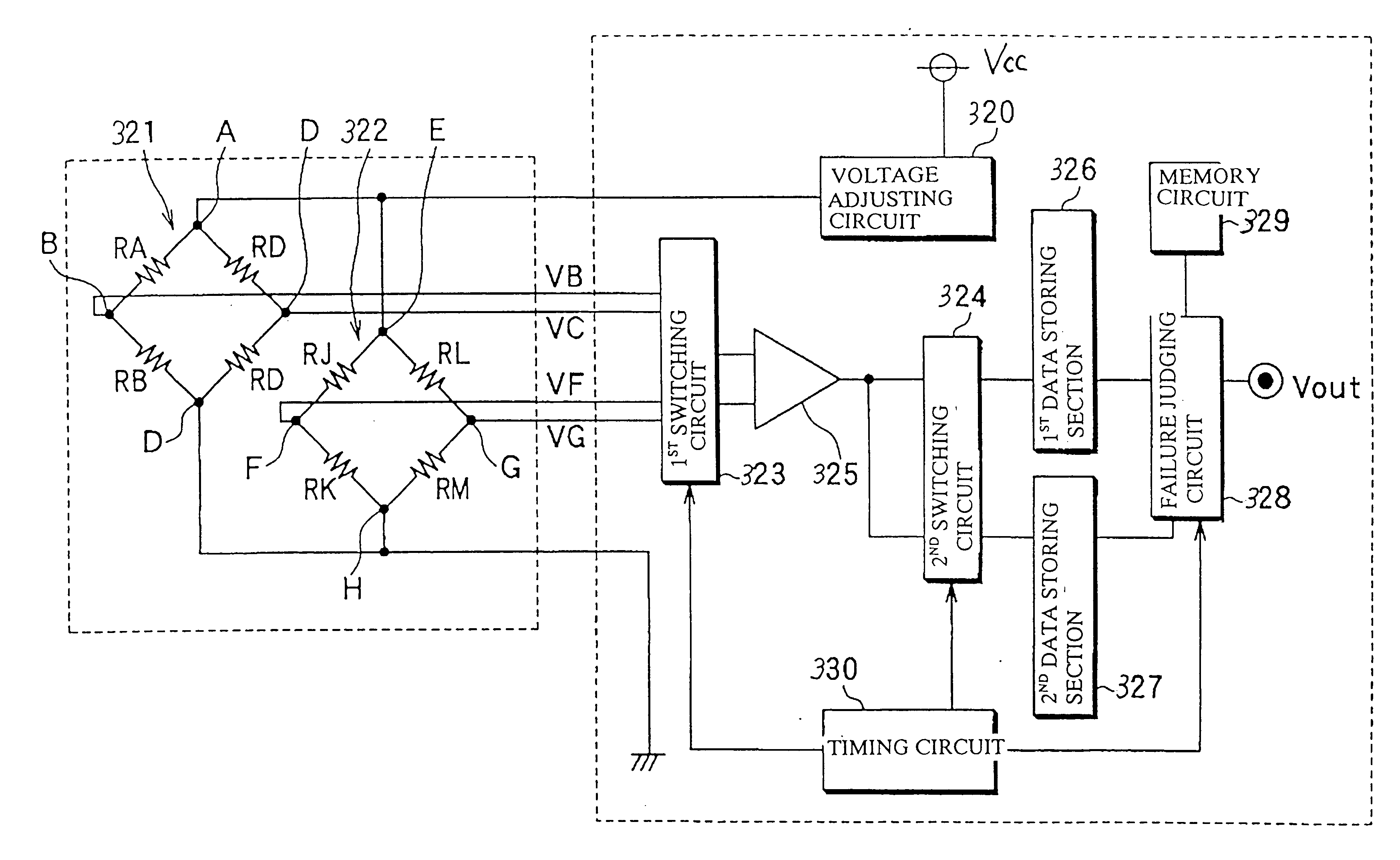
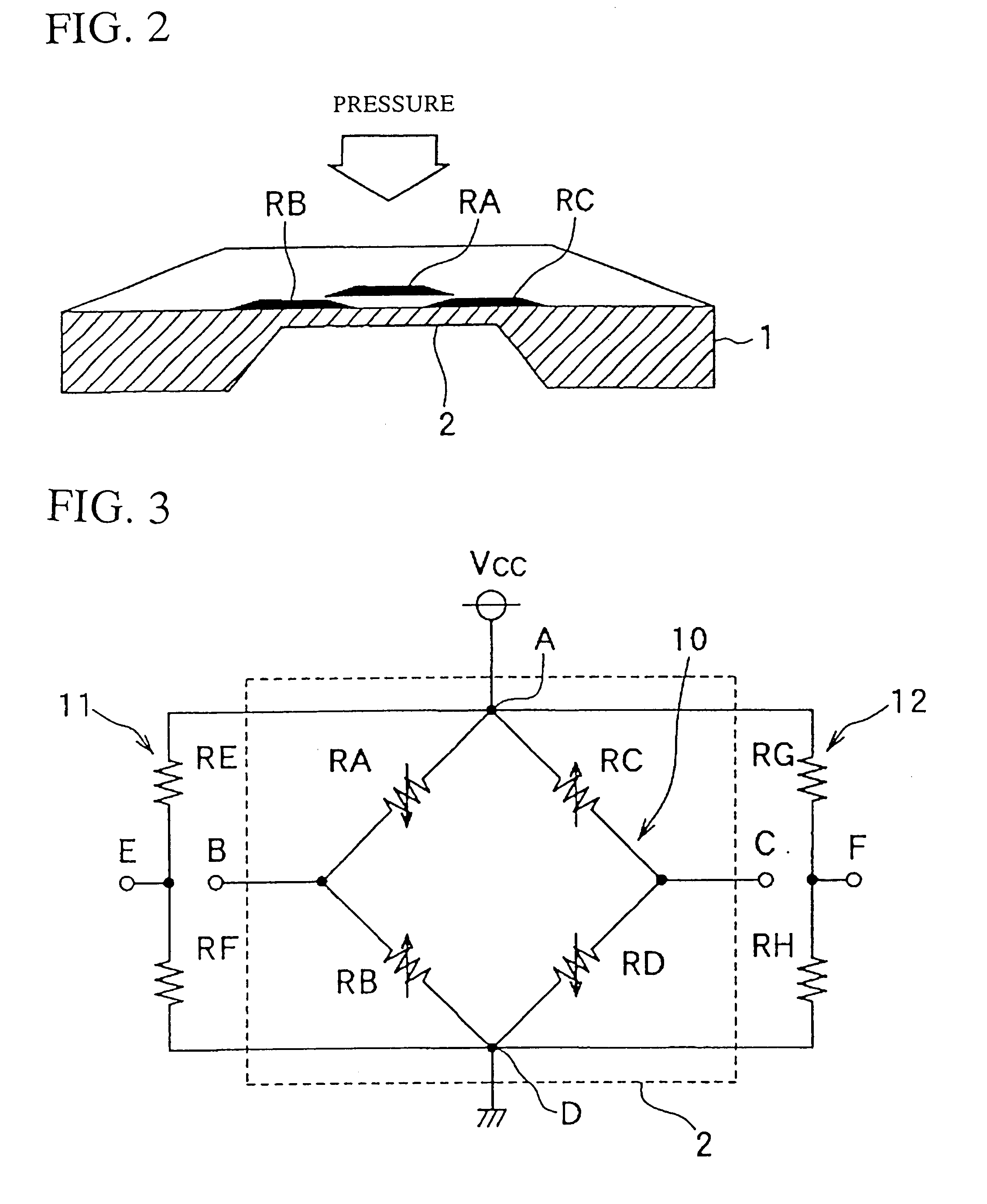
As shown in FIGS. 13A and 13B, the pressure sensor of the seventh embodiment comprises four diffused resistors RA.about.RD formed on a silicon substrate. An oxide film 3, serving as an insulating layer, is formed on the diffused resistors. Four thin-film resistors RN.about.RQ, for example made of a polysilicon, are formed on the oxide film 3. The four diffused resistors RA.about.RD constitute a pressure detecting bridge circuit 10. The four thin-film resistors RN.about.RQ constitute a failure detecting circuit. The thin-film resistors RN.about.RQ are located far from...

eighth embodiment

Next, an eighth embodiment of the present invention will be explained with reference to FIGS. 14A and 14B. A pressure sensor of the eighth embodiment uses a metal diaphragm. As shown in FIGS. 14A and 14B, the pressure sensor comprises a metal stem 50 having a circular diaphragm portion 50a, and a silicon substrate 51 bonded on the diaphragm portion 50a. The pressure sensor of the eighth embodiment detects a pressure based on a deformation of the diaphragm 50a and a silicon substrate 51.

The metal stem 50 is configured into a hollow cylindrical shape and made of a metal having a low thermal expansion coefficient (such as covar etc. having a thermal expansion coefficient similar to that of silicon). The metal stem 50 receives a pressurized medium entered from one end as shown by an arrow. Thus, a pressure of the pressurized medium is applied on the diaphragm portion 50a formed at the other end of the stem 50.

The silicon substrate 51 is fixed to the diaphragm portion 50a via a glass lay...

ninth embodiment

Next, a ninth embodiment of the present invention will be explained with reference to FIGS. 15A and 15B. FIG. 15A is a plan view showing a diaphragm portion of a pressure sensor of the ninth embodiment. FIG. 15B is a crosssectional view of the pressure sensor taken along a line E--E of FIG. 15A. The pressure sensor of the ninth embodiment differs from the pressure sensors of the above-described embodiment in that the failure detecting circuit is constituted by a capacitive sensor. The components similar to those disclosed in the abovedescribed embodiments are denoted by the same reference numerals and will not be explained.

As shown in FIG. 15A, the pressure sensor of the ninth embodiment comprises a capacitive sensor 53 serving as a failure detecting circuit in addition to four diffused resistors RA.about.RD constituting a pressure detecting circuit 10. The capacitive sensor 53 is provided at a central region of a diaphragm portion 2 of a silicon substrate 1. The electrical connecti...


PUM

PropertyMeasurementUnit
pressureaaaaaaaaaa
voltageaaaaaaaaaa
pressureaaaaaaaaaa

Abstract

A reference voltage generating circuit is constituted by resistors RE and RF each having a resistance not influenced by an application of pressure. The reference voltage generating circuit is connected between one and the other ends of a bridge circuit. A failure judgement of the bridge circuit is performed based on a comparison of a voltage difference VBC between two midpoints B and C of the bridge circuit and voltage differences VCE and VBE between a reference voltage level of the reference voltage generating circuit and the voltage levels of two midpoints B and C.

Description

The present invention relates to a physical or dynamic quantity detecting apparatus and a sensor failure or abnormality detecting system incorporated in this apparatus.A conventional pressure sensor comprises a semiconductor substrate with a thin diaphragm portion. Two pressure detecting elements (i. e., gauge resistors) are formed in a central region of this diaphragm portion, and another two pressure detecting elements are formed in a peripheral portion of this diaphragm portion. These four pressure detecting elements are arranged to form a Wheatstone's bridge circuit. When a pressure is applied on the diaphragm portion, the resistance of each pressure detecting element varies due to a piezoresistance effect. A significant difference (i.e., an output voltage) appears between a midpoint of the pressure detecting elements in the central region and a midpoint of the pressure detecting elements in the peripheral region. The pressure sensor amplifies and adjusts this output voltage app...

Claims


Application Information

Patent Timeline
Patent Type & Authority Patents(United States)
IPC IPC(8): G01L1/22G01L9/02G01L1/20
CPCG01D3/08G01L9/0051G01L9/02G01R17/10G01L27/007G01L9/0054
Inventor OBA, NOBUKAZUMURAKAMI, YOSHIFUMITANIZAWA, YUKIHIKOTANAKA, HIROAKIISHIO, SEIICHIROTOYODA, INAOSUZUKI, YASUTOSHI
Owner DENSO CORP
Why Eureka
Try Eureka