High-frequency power supply system

a high-frequency power supply and power supply technology, applied in the field of high-frequency power supply systems, can solve the problems of destroying damaged components further, reducing the reflection coefficient, and not being able to detect such anomalies in the conventional high-frequency power supply system

Inactive Publication Date: 2007-05-31
DAIHEN CORP
View PDF4 Cites 139 Cited by
  • Summary
  • Abstract
  • Description
  • Claims
  • Application Information

AI Technical Summary

Benefits of technology

[0011] It is therefore an object of the present invention to provide a high-frequency power supply

Problems solved by technology

Meanwhile in the load L, the damaged component can be destroyed further by continued supply of the high frequency power.
However, the conventional high-frequency power supply system is not designed to detect such an anomaly as described above or run a safety function.
However, a problem with this method is that the reflection coefficient should exceed the reference value in

Method used


Image

  • High-frequency power supply system
  • High-frequency power supply system
  • High-frequency power supply system

Examples


embodiment 1

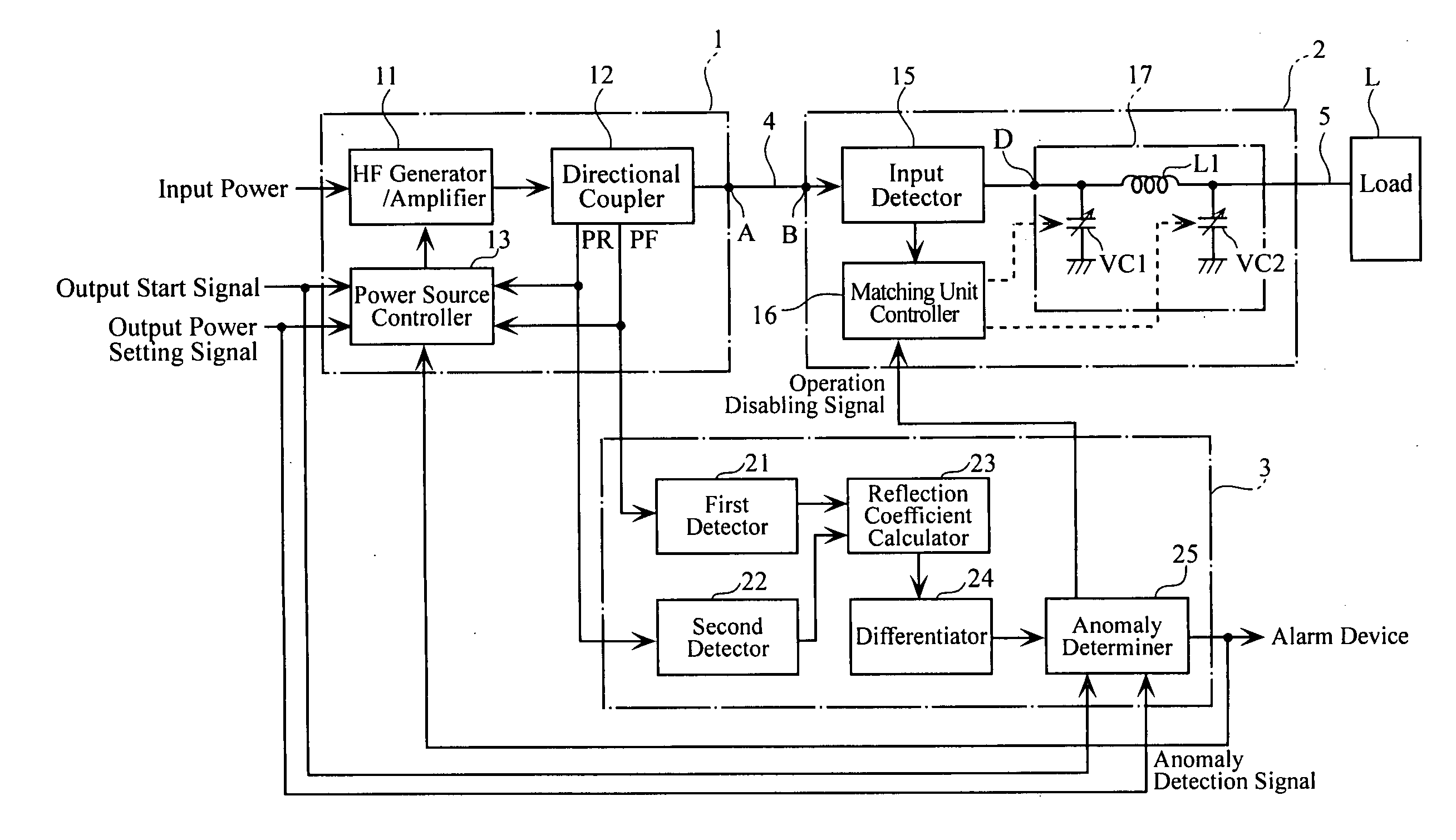
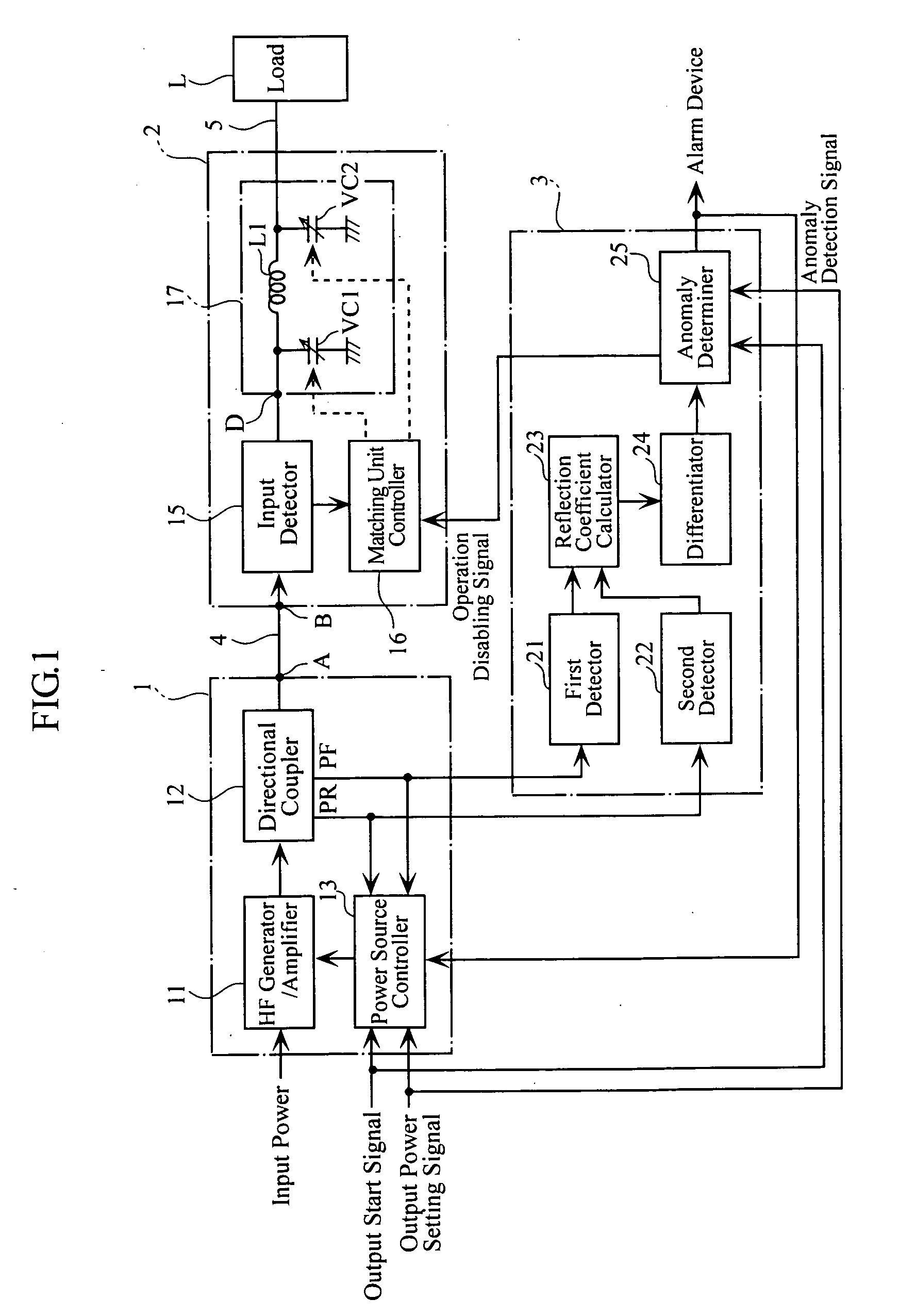
[0103]FIG. 1 shows a configuration of a high-frequency power supply system of the present invention. The system supplies high-frequency power necessary for processing such works as semiconductor wafers and liquid crystal substrates, for performing e.g. plasma etching. The high-frequency power supply system includes a high-frequency power source 1, an impedance matching unit 2, an anomaly detector 3, a transmission line 4, a load connecting section 5 and a load L which is provided by a plasma processing apparatus.

[0104] The high-frequency power source 1 is connected with the impedance matching unit 2 via the transmission line 4 provided by e.g. a coaxial cable. The impedance matching unit 2 is connected with the load L (a plasma processing apparatus for example) via the load connecting section 5 provided by e.g. a copper plate which is shielded against electromagnetic leakage. In addition, the high-frequency power source 1 is connected with the anomaly detector 3. Note that although...

embodiment 2

[0169] For this reason, in the present Embodiment 2, both the differential value dΓ / dt of the reflection coefficient Γ and the differential value dZ / dt of the impedance Z are obtained whereby anomalies occurring specifically in the load L are identified and detected.

[0170] Since the anomaly determiner 25 detects anomalies based on the differential value dΓ / dt of the reflection coefficient Γ and the impedance differential value dZ / dt, detection is made instantaneously, or more quickly than in methods which rely only on the magnitude of the reflection coefficient Γ or in methods which depend upon the magnitude of the impedance Z.

[0171] Now, description will be made in more specific details. Once the high-frequency power source 1 starts supplying high-frequency power, the high-frequency power source 1 separately detects the forward wave PF and the reflected wave PR of the high frequency wave, and inputs detected signals to the anomaly detector 3. Meanwhile, the impedance matching unit...

embodiment 4

[0185] As described, in Embodiment 4, anomaly occurrence determination is made not only on the basis of the reflection coefficient differential value dΓ / dt but also on the basis of the reflection coefficient Γ. For example, the system determines that an anomaly exists if the reflection coefficient differential value dΓ / dt is large and the reflection coefficient Γ is large.

[0186] In the above, the anomaly determiner 25 determines presence of an anomaly using an AND operation between the comparison result from the first comparator 28 and the comparison result from the second comparator 29, i.e. when the differential value dΓ / dt of the reflection coefficient Γ has exceeded the first reference value and the reflection coefficient Γ has exceeded the second reference value. Alternatively, the determiner may use an OR operation between the comparison result from the first comparator 28 and the comparison result from the second comparator 29. Specifically, the anomaly determiner may determi...


PUM


Abstract

A high-frequency power supply system includes an anomaly detector 3 which detects an anomaly occurring in a circuit on the side of a load L as from an outputting end A of a high-frequency power source 1. The anomaly detector 3 includes a first detector 21 which detects a voltage value Vf of a high-frequency forward wave, a second detector 22 which detects a voltage value Vr of a high-frequency reflected wave, a reflection coefficient calculator 23 and a differentiator 24 which calculate a reflection coefficient differential value dΓ/dt from the forward wave voltage value Vf and the reflected wave voltage value Vr, and an anomaly determiner 25 which determines of an occurrence of an anomaly based on the reflection coefficient differential value dΓ/dt. When the anomaly detector 3 outputs an anomaly detection signal to the high-frequency power source 1, high-frequency power source 1 stops its power output operation.

Description

TECHNICAL FIELD [0001] The present invention relates to a high-frequency power supply system for supplying high-frequency electric power to a load, such as a plasma processing apparatus, via an impedance matching unit. BACKGROUND ART [0002]FIG. 23 shows a general configuration of a conventional high-frequency power supply system. The power supply system includes a high-frequency power source 51 to output high-frequency power, an impedance matching unit 53 for matching the input impedance of the high-frequency power source 51 with the load impedance, and a load L which is e.g. a plasma processing apparatus. The impedance matching unit 53 is connected with the high-frequency power source 51 via a transmission line 52 provided by a coaxial cable. The load L is connected with the impedance matching unit 53 via a load connecting section 54 consisting of e.g. copper plates and shielded to prevent electromagnetic leakage. [0003] The high-frequency power source 51 is an apparatus for supply...

Claims


Application Information

Patent Timeline
IPC IPC(8): H02H3/00H03H7/40H05H1/46
CPCH01J37/32174H01J37/32935H03H7/40H05H1/46
Inventor KOTANI, HIROYUKITAKEI, HIROTAKAIBUKI, YOSHIFUMIOICHI, HIROAKI
Owner DAIHEN CORP
Why Eureka
Try Eureka