Automatic wire stretching device based on pressure sensory control
A sensor control and pressure sensor technology, applied in textiles and papermaking, etc., can solve the problems of low efficiency, labor and time-consuming, unable to meet production needs, etc., and achieve the effect of good wire drawing effect
- Summary
- Abstract
- Description
- Claims
- Application Information
AI Technical Summary
Problems solved by technology
Method used
Image
Examples
Embodiment 1
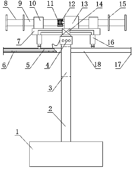
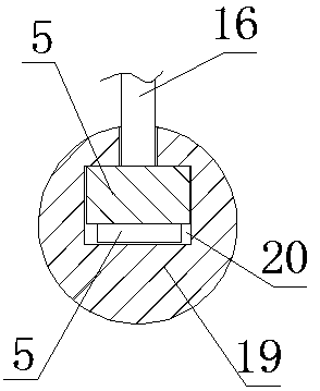
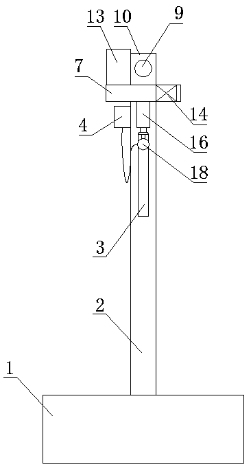
[0027] see Figure 1-3 , an automatic wire stretching device based on pressure sensing control, comprising a counterweight base 1 and a column 2 arranged on the base 1, a top seat 7 is provided on the top of the column 2, a roller beam 9 is provided on the top of the top seat 7, and the roller Axis crossbeam 9 is arranged on described top base 7 by two bearing blocks 10, and is provided with stepping motor 13 driving control its rotation on its side, and stepping motor 13 is fixed on top base 7, and its output shaft is provided with The gear 12 meshed with the ring gear 11 on the roller beam 9, the stepper motor 13 is connected with the controller 4 arranged on the column 2, and the stepper motor 13 is controlled by the controller 4 to drive the roller beam 9 to rotate. Annular baffles 15 are arranged at both ends of the roller beam 9 to limit the position to prevent the reel from slipping, and the surface of the roller beam 9 between the two annular baffles 15 is covered with...
Embodiment 2
[0031] See attached Figure 4-6 The difference between this embodiment and Embodiment 1 is that the drive mechanism includes an electromagnet 22 fixedly sleeved on the column 2, the electromagnet 22 is connected to the power supply through the controller 4, and the controller 4 controls the electromagnet 22. Control comprises the control of voltage, electric current and frequency, and electromagnet 22 is positioned at stretch rod 18 below, and the position corresponding to electromagnet 22 on stretch rod 18 is provided with hoop 23, and hoop 23 is sleeved outside column 2 and is connected with described stretch rod 18. Rod 18 is fixedly connected, see Figure 5 and 6 , the iron ring 23 has a groove 26 corresponding to the stretching rod 18, the center of the iron ring 23 has a central hole 27 matched with the column 2, the groove 26 runs through the central hole 27 along its radial center, and the stretching rod 18 is placed in the longitudinal chute 3 of the column 2, and i...
PUM
 Abstract
Description
Claims
Application Information
 - R&D
- Intellectual Property
- Life Sciences
- Materials
- Tech Scout
- Unparalleled Data Quality
- Higher Quality Content
- 60% Fewer Hallucinations
Browse by: Latest US Patents, China's latest patents, Technical Efficacy Thesaurus, Application Domain, Technology Topic, Popular Technical Reports.
© 2025 PatSnap. All rights reserved.Legal|Privacy policy|Modern Slavery Act Transparency Statement|Sitemap|About US| Contact US: help@patsnap.com


