
A geothermal well wall cleaning device

A technology for cleaning devices and geothermal wells, which is applied in wellbore/well parts, cleaning equipment, earthwork drilling and mining, etc., can solve the problems of low stability of geothermal well wall cleaning devices, and achieve improved stability and safety, transmission The structure is stable and the effect of avoiding shaking

Active Publication Date: 2021-06-15
郭山河
View PDF5 Cites 0 Cited by
  • Summary
  • Abstract
  • Description
  • Claims
  • Application Information

AI Technical Summary

Problems solved by technology

[0003] The purpose of the present invention is to provide a geothermal well wall cleaning device, which has the advantage of high stability and solves the problem of low stability of common geothermal well wall cleaning devices

Method used


Image

  • A geothermal well wall cleaning device
  • A geothermal well wall cleaning device

Examples


no. 1 approach

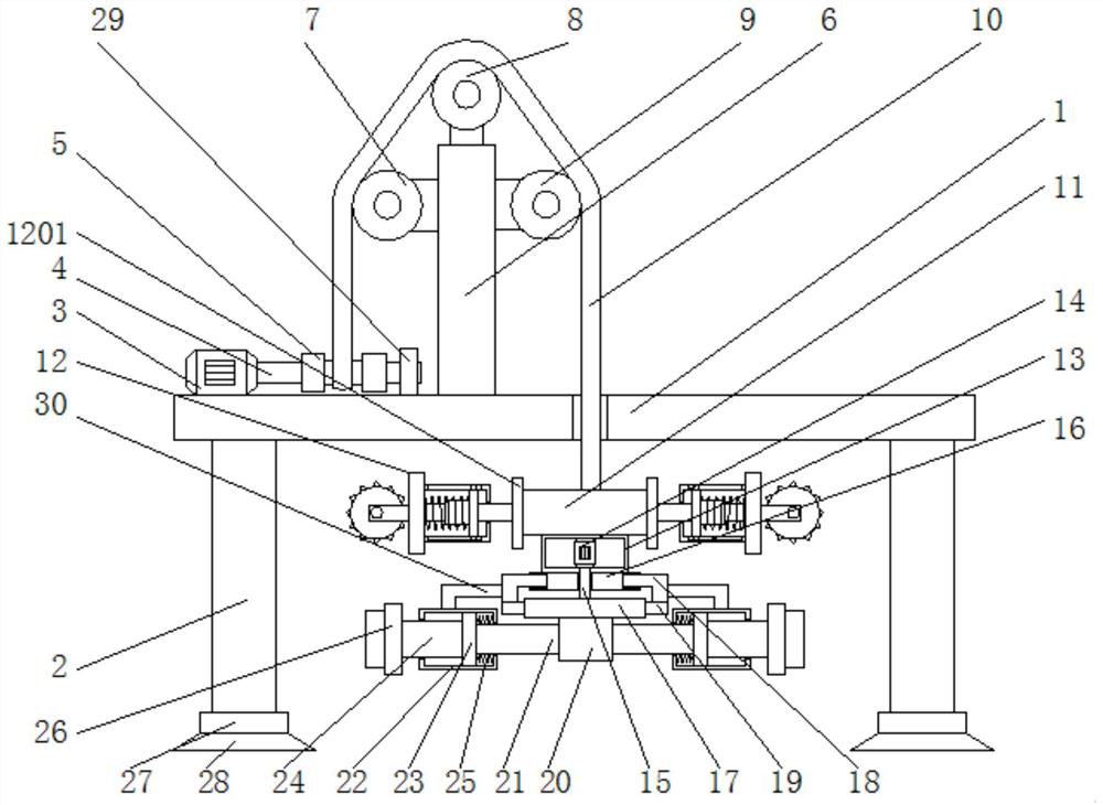
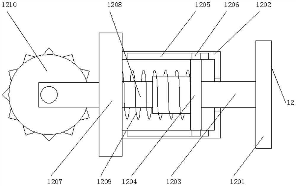
[0017] First implementation: see figure 1 , a geothermal well wall cleaning device, comprising a fixed plate 1, the left and right sides of the bottom of the fixed plate 1 are fixedly connected with a support plate 2, by setting the support plate 2, it plays the role of supporting the fixed plate 1, the support plate 2 The bottom is fixedly connected with a shelving block 27, and the bottom of the shelving block 27 is fixedly connected with a shock-absorbing pad 28. By setting the shelving block 27 and the shock-absorbing pad 28, the shock resistance of the whole device is improved, and the internal components of the cleaning device are avoided from being damaged by vibration. The left side of the top of the fixed plate 1 is fixedly connected with a rotating motor 3, the output shaft of the rotating motor 3 is fixedly connected with a rotating shaft 4, and the surface of the rotating shaft 4 is fixedly connected with a winding wheel 5, and the surface of the rotating shaft 4 is...

no. 2 approach

[0021] The second embodiment: a geothermal well wall cleaning device, including a fixed plate 1, the left and right sides of the bottom of the fixed plate 1 are fixedly connected with a support plate 2, and the left side of the top of the fixed plate 1 is fixedly connected with a rotating Motor 3, the output shaft of the rotating motor 3 is fixedly connected with a rotating shaft 4, the surface of the rotating shaft 4 is fixedly connected with a winding wheel 5, and the top of the fixed plate 1 is fixed on the right side of the rotating shaft 4 Connected with a stabilizing plate 6, the top on the left side of the stabilizing plate 6 is fixedly connected with a first runner 7, the top of the stabilizing plate 6 is fixedly connected with a second runner 8, and the top on the right side of the stabilizing plate 6 is fixed A third runner 9 is connected, the surface of the reel 5 is wound with a first fixed rope 10, and the end of the first fixed rope 10 away from the reel 5 passes ...


PUM


Abstract

The invention discloses a geothermal well wall cleaning device, comprising a fixed plate, the left and right sides of the bottom of the fixed plate are fixedly connected with support plates, the left side of the top of the fixed plate is fixedly connected with a rotating motor, and the output shaft of the rotating motor is fixed A rotating shaft is connected, and a winding wheel is fixedly connected to the surface of the rotating shaft. The present invention installs through fixed blocks, movable devices, connecting plates, connecting rods, movable plates, mounting plates, telescopic blocks, buffer springs, rolling guide wheels, stable motors, stable rotating shafts, annular plates, rotating blocks, connecting blocks, rotating plates, Block, fixed rod, stabilizing block, mounting plate, connecting spring and cleaning brush cooperate with each other to achieve a high stability effect, solve the problem of low stability of the geothermal well wall cleaning device, make the transmission structure more stable, and improve the The stability and safety of the cleaning process make the cleaning efficiency high, greatly improve the work efficiency, and bring great convenience to users.

Description

technical field [0001] The invention relates to the technical field of geothermal well wall cleaning, in particular to a geothermal well wall cleaning device. Background technique [0002] Geothermal wells refer to methods and devices for generating electricity from geothermal energy with a depth of about 3,500 meters or hot spring water with a water temperature greater than 30°C. It belongs to high-temperature geothermal; 90℃~150℃, existing in the form of mixture of water and steam, etc., belongs to medium-temperature geothermal; Low temperature geothermal, after completion of geothermal well, due to the long-term use of circulating fluid during drilling, the circulating fluid will form mud skin on the well wall, if not handled properly, it will directly affect the next step of well cleaning operation, common geothermal well wall cleaning The stability of the device is low. Due to the unstable design of the transmission structure, the cleaning process is poor in stability ...

Claims


Application Information

Patent Timeline
Patent Type & Authority Patents(China)
IPC IPC(8): E21B37/00
CPCE21B37/00
Inventor 金峰
Owner 郭山河
Learn More