Walking power output mechanism of combine-harvester

A combine harvester and walking power technology, applied in the field of combine harvester and combined harvester walking power output mechanism, can solve the problems of high return on investment, difficult steering, and single-season crops cannot meet the user's income requirements, so as to improve the Longevity and reliability, stable crawler drive structure, and improved cross-area performance

Active Publication Date: 2017-02-22
JINHUA VOCATIONAL TECH COLLEGE
View PDF6 Cites 1 Cited by
  • Summary
  • Abstract
  • Description
  • Claims
  • Application Information

AI Technical Summary

Problems solved by technology

On the other hand, users have higher and higher requirements for the return on investment of combine harvesters, and the harvest of single-season crops can no longer meet the user's income requirements
[0003] The walking power output mechanism of the combine harvester here is mainly used to realize the walking, braking and steering of the entire combine harvester by driving the crawler belt, but there are currently big problems due to the unreasonable mechanism of the entire walking power output mechanism. When one side When the track brakes, the walking power output mechanism drives it to produce complete sliding friction against the ground when turning, which seriously damages the soil of the paddy field. When it turns, the track on the braking side will cause soil accumulation, resulting in difficulty in turning. And lead to insufficient fuel combustion. At the same time, due to the demand for combine harvesters in the market, under the same chassis aspect ratio, increasing the weight of the whole machine will make steering more difficult. Once the load increases, the resistance of one side of the track increases. It will cause the engine to stall. At the same time, the existing walking power output mechanism still has the disadvantages of difficulty in walking on wet and soft fields and uneven ground, easy to sink, and poor adaptability.

Method used


Image

  • Walking power output mechanism of combine-harvester
  • Walking power output mechanism of combine-harvester
  • Walking power output mechanism of combine-harvester

Examples


Embodiment 1

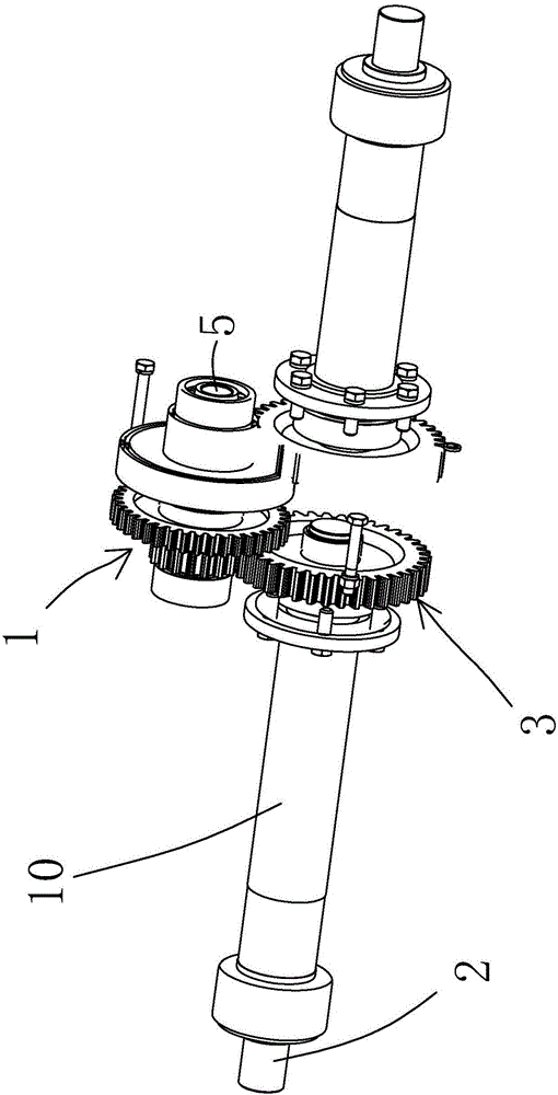
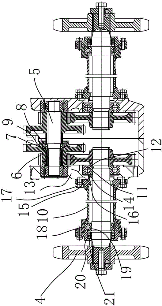
[0029] Such as figure 1 and figure 2 As shown, the walking power output mechanism of the combine harvester includes a power input assembly 1, an output shaft 2, a drive gear assembly 3 and a track wheel assembly 4, where the power input assembly 1 is used to provide the overall power input, and the power input assembly The assembly 1 includes an input shaft 5, an input gear 6, a roller bearing 7, a third rolling bearing 8 and a limiting member 9. The input gear 6 is connected to the input shaft 5, and the rolling bearing 7 and the third rolling bearing 8 are arranged on the input gear 6. Between the input shaft 5 and the limiting member 9 is arranged on the outer end of the input gear 6 and is used to maintain the position of the roller bearing 7 and the third rolling bearing 8, and is used to isolate the two between the roller bearing 7 and the third rolling bearing 8 There is a stopper, and the installation position of the roller bearing 7 and the third rolling bearing 8 c...

Embodiment 2

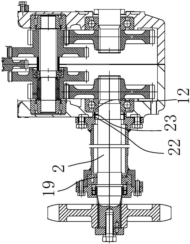
[0033] Most of the structure of this embodiment is the same as Embodiment 1, as image 3 As shown, because it is symmetrical here, half of it is shown. The difference is that the first shaft assembly 11 includes a transverse elastic member 22 and a first rolling bearing 12, and a stepped groove 23 is opened at the inner lower end of the press fit member 15. The elastic member 22 is arranged in the step groove 23, and the two ends of the transverse elastic member 22 respectively act on the first rolling bearing 12 and the stepped groove 23 and are used to adjust the lateral clearance of the first rolling bearing 12. Here, in order to make the first rolling bearing 12 The adjustment is more reasonable. Here, the first rolling bearing 12 is adjusted through the transverse elastic member 22. Here, since one end of the transverse elastic member 22 is pressed against the step groove 23, when the press fit part 15 is installed, the press fit part 15 Adaptively adjust the position of ...

Embodiment 3

[0035] Most of the structure of this embodiment is the same as Embodiment 2, as Figure 4 As shown, because it is symmetrical here, half of it is shown. The difference is that the second shaft assembly 29 also includes a longitudinal elastic member 24, and there is a longitudinal groove for the longitudinal elastic member 24 to be placed next to the second rolling bearing 19 and the dome body 18. 25. The longitudinal elastic member 24 leans against the lower cover surface of the dome body 18 acting on the second rolling bearing 19. In order to make the gap adjustment in the longitudinal direction more reasonable, here the longitudinal elastic member 24 abuts against the dome body 18 When installing the lower cover of the round cover body 18, the longitudinal gap between the sleeve member 10 and the output shaft 2 can be adjusted by the longitudinal elastic member 24, thereby realizing the adjustment of the longitudinal gap.


PUM


Abstract

The invention belongs to the technical field of agricultural equipment, and provides a walking power output mechanism of a combine-harvester. The walking power output mechanism comprises a power input end assembly, an output shaft, a driving gear assembly and a crawler wheel assembly, a sleeve part is arranged on the exterior of the output shaft between the crawler wheel assembly and the driving gear assembly, the output shaft is arranged in the sleeve part in a penetrating mode, and an axial coordination assembly used for adjusting the running clearance distance is arranged between the output shaft and the sleeve part. The walking power output mechanism has the advantages that by means of the axial coordination assembly, it is guaranteed that the caterpillar drive structure is stable and is not likely to fail or damage, the maintenance cost can be reduced, the running speed of the combine-harvester on a smooth-riding surface is increased, and adaptability to complex field blocks is improved, and the cross-regional operation property of the combine-harvester is greatly improved; meanwhile, a longitudinal adjusting bearing, a first rolling bearing and a second rolling bearing can prolong the abrasion life by adjusting the clearance matched with the output shaft, the service life is further prolonged, and the reliability is further improved.

Description

technical field [0001] The invention belongs to the technical field of agricultural equipment and relates to a combine harvester, in particular to a walking power output mechanism of the combine harvester. Background technique [0002] Agricultural machinery refers to various machinery used in crop planting and animal husbandry production, as well as in the primary processing and handling of agricultural and animal products. Agricultural machinery also includes crop harvesting machinery, agricultural transport machinery, etc. At present, driven by factors such as national policy guidance and the transfer of rural labor force, the speed of domestic land transfer has accelerated, the area of ​​a single plot has increased, the roads for machine farming have become wider, and the yield per mu of crops has continued to increase. Users have higher and higher requirements on the working efficiency of combine harvesters. On the other hand, users have higher and higher requirements...

Claims


Application Information

Patent Timeline
IPC IPC(8): B60K17/28B62D55/00
CPCB60K17/28B62D55/00
Inventor 马广王志明周璇马春晓
Owner JINHUA VOCATIONAL TECH COLLEGE
Why Eureka
Try Eureka