
Supporting assembly for steam pipeline

A technology for steam pipelines and supporting components, which is applied to measuring devices, instruments, etc., can solve the problems that thermal stress and bending stress cannot offset each other, are not easy to find, and have hidden dangers, and achieve the effect of preventing pipelines from falling at high altitudes.

Active Publication Date: 2019-03-12
常州市长江热能有限公司
View PDF12 Cites 0 Cited by
  • Summary
  • Abstract
  • Description
  • Claims
  • Application Information

AI Technical Summary

Problems solved by technology

[0002] In the steam production site, since the temperature of the steam transported is above 100°C, the transportation pipeline is in a high-temperature environment for a long time, and thermal deformation will occur after a long period of use, especially at the bend of the pipeline, where thermal stress and Bending stresses cannot offset each other, and the degree of deformation is higher. The transportation pipeline is usually spliced ​​with seamless steel pipes to form a steam pipeline network. The deformation of the pipeline will cause the center of gravity of the steam pipeline to shift. This shift process exists at a higher place, and the relevant staff is not easy to find out. Therefore, the distance measuring sensor is often used to monitor the deformation of the steam pipeline in real time. When the distance measuring sensor is used Fitted with steam pipes, its own plastic shell is affected by high temperature and is easily damaged by melting, which poses a certain safety hazard

Method used


Image

  • Supporting assembly for steam pipeline
  • Supporting assembly for steam pipeline
  • Supporting assembly for steam pipeline

Examples


Embodiment Construction

[0021] Embodiments of the present invention are described in detail below, examples of which are shown in the drawings, wherein the same or similar reference numerals designate the same or similar elements or elements having the same or similar functions throughout. The embodiments described below by referring to the figures are exemplary only for explaining the present invention and should not be construed as limiting the present invention. On the contrary, the embodiments of the present invention include all changes, modifications and equivalents coming within the spirit and scope of the appended claims.

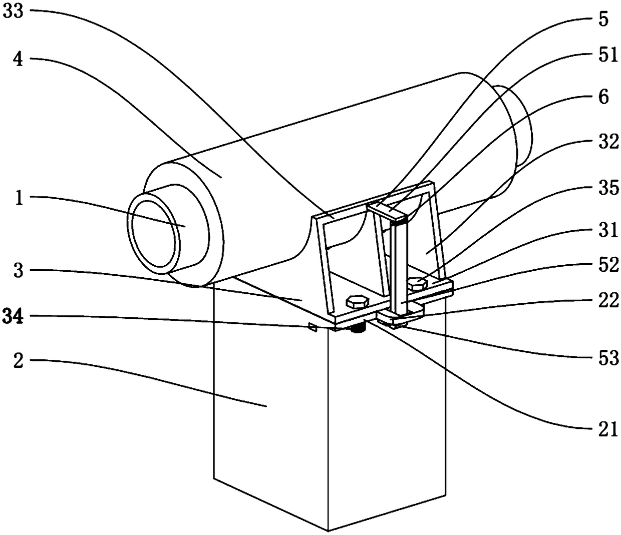
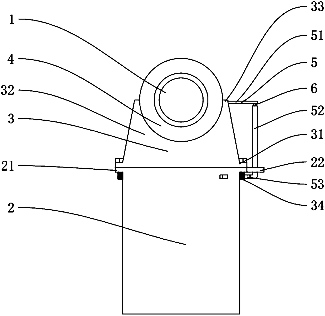
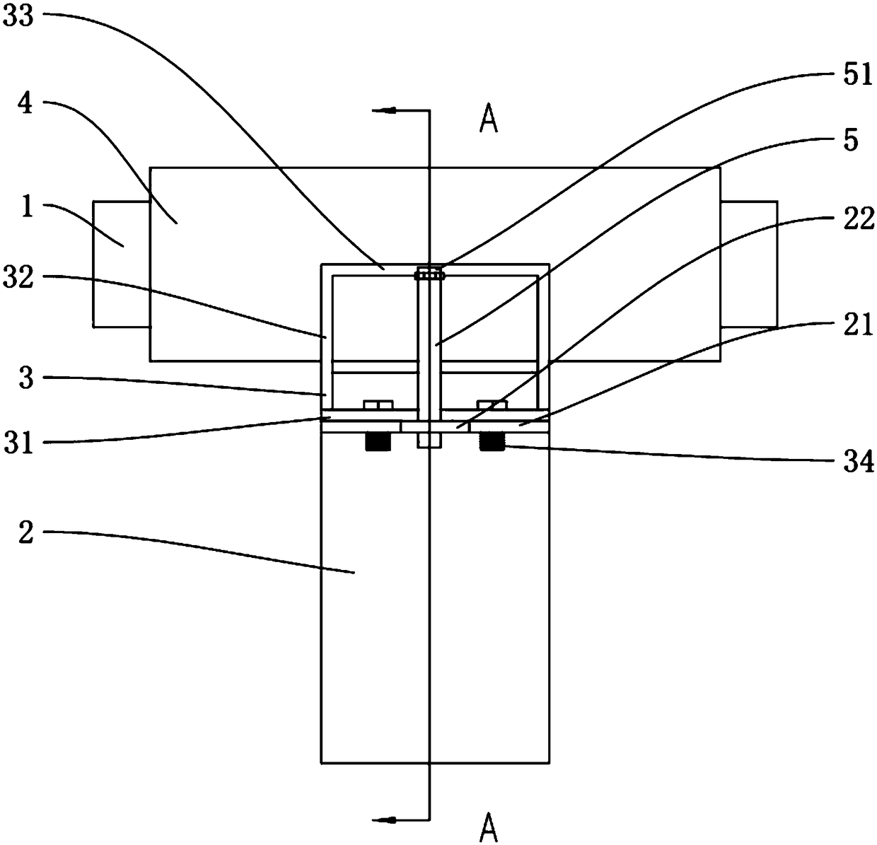
[0022] like Figure 1 to Figure 5 As shown, the present invention provides a steam pipeline network, including a steam pipeline 1, a pillar 2 supporting the steam pipeline 1, and a support assembly 3 connected to the steam pipeline 1 and the pillar 2. The outer wall of the steam pipeline 1 is fitted with a The insulation layer 4 and the distance measuring connecting frame...


PUM


Abstract

The invention provides a supporting assembly for a steam pipeline. The supporting assembly is installed between the steam pipeline sleeved with a heat preservation layer and a support column and comprises a fixed base, supporting plates and a plurality of fixed rods, and the fixed base, the supporting plates and the fixed rods are of an integrally-formed structure; the heat preservation layer is in cooperative lap joint with the interior of the arc surfaces of the upper ends of the supporting plates, the fixed rods are connected to the upper ends of all the supporting plates, and a measuring device is inserted into the fixed rods and comprises a measuring rod, a linkage rod, a distance measuring rod and a distance measuring sensor; a rotary rod is inserted in the column, the linkage rod ishinged to the rotary rod, a magnetic block is fixedly installed on the linkage rod and is in attraction connection with the distance measuring rod, the column is provided with a distance measuring blind hole, the distance measuring sensor is installed at the hole bottom of the distance measuring blind hole, the end, away from the linkage rod, of the distance measuring rod is cooperatively inserted in the distance measuring blind hole, the distance measuring sensor is utilized for monitoring the thermal deformation of the steam pipeline in real time, and the phenomenon of pipeline falling caused by thermal deformation is avoided.

Description

technical field [0001] The invention relates to the technical field of steam pipeline detection, in particular to a steam pipeline support assembly. Background technique [0002] In the steam production site, since the temperature of the steam transported is above 100°C, the transportation pipeline is in a high-temperature environment for a long time, and thermal deformation will occur after a long period of use, especially at the bend of the pipeline, where thermal stress and Bending stresses cannot offset each other, and the degree of deformation is higher. The transportation pipeline is usually spliced ​​with seamless steel pipes to form a steam pipeline network. The deformation of the pipeline will cause the center of gravity of the steam pipeline to shift. This shift process exists at a higher place, and the relevant staff is not easy to find out. Therefore, the distance measuring sensor is often used to monitor the deformation of the steam pipeline in real time. When t...

Claims


Application Information

Patent Timeline
Patent Type & Authority Applications(China)
IPC IPC(8): G01B21/32
CPCG01B21/32
Inventor 牟腾秦龙钱乃刚
Owner 常州市长江热能有限公司
Learn More