A construction and installation method for steel beams in shafts

An installation method and technology of steel beams, applied in the direction of hoisting equipment safety devices, hoisting devices, etc., can solve the problems of limited space inside caverns and shafts, consume a lot of construction work time, and unfavorable wire rope protection, so as to avoid falling from high places Risk, reduce safety risk and construction difficulty, avoid frequent adjustment of direction and unsatisfactory effect of force

Active Publication Date: 2021-11-30
SINOPEC NINGBO ENG +2
View PDF9 Cites 0 Cited by
  • Summary
  • Abstract
  • Description
  • Claims
  • Application Information

AI Technical Summary

Problems solved by technology

[0005] The disadvantages of the internal scaffolding installation process are: due to the limited internal space of the cavern and the shaft, the height of the scaffolding is greater than 100m, and a large amount of scaffolding materials are required to assemble and disassemble the scaffolding, which consumes a lot of construction work time, the cycle is long, the construction is difficult, and the safety risk high
The disadvantages of the tower installation process are: the long-distance lifting and lowering of the working steel platform and the hanging basket in the shaft is easy to shake, the stability is poor, and the hot work process is not conducive to the protection of the wire rope, and the wire rope is prone to breakage due to fire, and the safety risk of falling is high. ; Hoisting from the bottom to the top is not easy to control and prone to hoisting accidents; the use of wellhead towers and other methods to input temporary materials, a lot of tooling, high construction costs and long periods

Method used


Image

  • A construction and installation method for steel beams in shafts

Examples


Embodiment Construction

[0022] The present invention will be further described in detail below in conjunction with the accompanying drawings and embodiments.

[0023] The construction and installation method of the steel beam in the vertical shaft of the embodiment comprises the following steps:

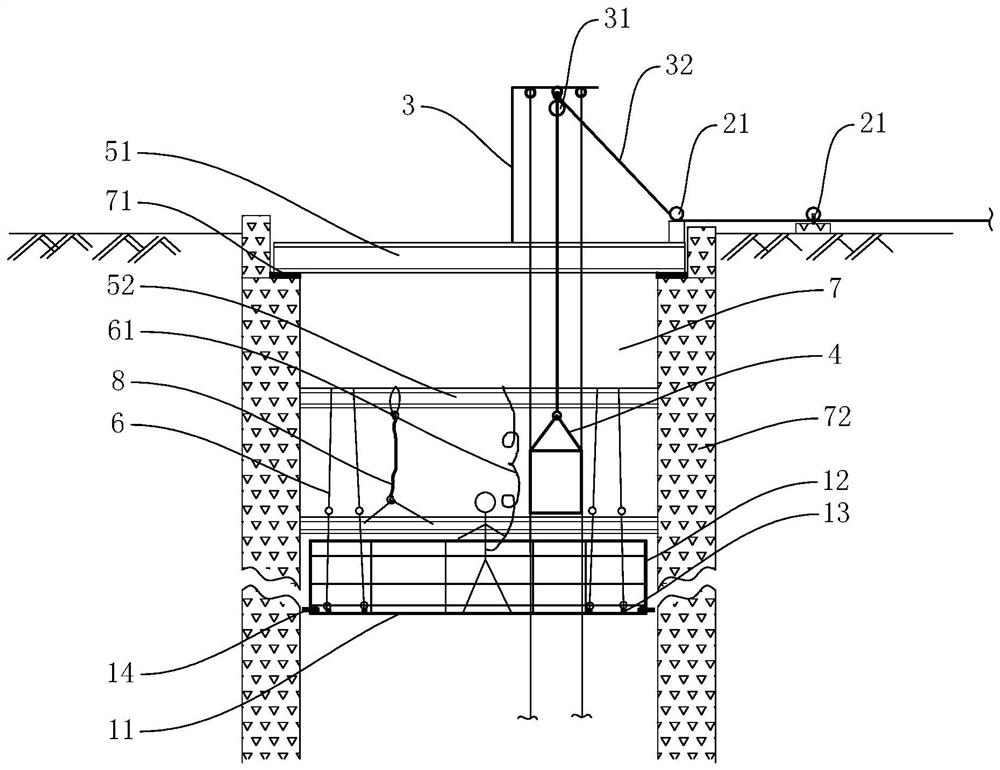
[0024] (1) Making steel platform for operation, see figure 1 , the working steel platform includes a base 11, a guardrail 12 and four lifting lugs 13, the guardrail 12 and the four lifting lugs 13 are respectively fixed on the upper side of the base 11, the four lifting lugs 13 are located inside the guardrail 12, and the base 11 consists of two It is formed by splicing symmetrical steel plates, and the two steel plates are connected by bolts, and the peripheral wall of the base 11 is equipped with a plurality of jacking wires 14 (at least 8);

[0025] (2) Arrange 3 winches (not shown in the figure) and multiple ground guide pulleys 21 around the shaft mouth, among which the bearing capacity of 2 winches m...


PUM


Abstract

In the method for construction and installation of steel beams in a vertical shaft disclosed by the present invention, the working steel platform is reliably fixed on the inner wall of the vertical shaft through a plurality of jacking wires to prevent the working steel platform from shaking; during the downward movement of the working steel platform, the number of people on the platform can be reduced to the greatest extent , to avoid accidental safety accidents; the method of the present invention adopts an independent winch system for the working steel platform and the hanging basket, so that the layout of the shaft head tooling facilities is more concise and easy to operate, thereby ensuring the stable suspension and lifting of the working steel platform and avoiding high places. The risk of falling, providing the maximum working space, better protecting the wire rope, preventing the damage of the wire rope, and reducing the impact of ground personnel, equipment, and environment on the construction operation in the shaft; the method of the invention is safe, reliable, operable, high in efficiency, and low in cost. , can effectively solve the suspension and lifting problems of the operating steel platform in the shaft, significantly reduce the safety risk and construction difficulty of the steel beam construction in the shaft, improve the operation efficiency, and promote the technical progress of shaft installation and construction.

Description

technical field [0001] The invention relates to the technical field of shaft construction, in particular to a construction and installation method for steel beams in shafts. Background technique [0002] At present, using underground caverns to store crude oil has become the development trend of national crude oil reserves. The vertical shaft of the underground cavern is dug vertically above the cavern, and the operation of entering and exiting the crude oil in the cavern is completed through the shaft. [0003] After the shaft is excavated, the steel structure, pipes and accessories inside the shaft need to be installed. In the construction of underground caverns, the installation of steel structures, pipes and accessories inside the shaft is a key link. The inner wall structure of the shaft of the underground cavern is divided into the upper masonry section and the lower rock section. The blasting construction causes the inner diameter of the shaft to be uneven, and the ...

Claims


Application Information

Patent Timeline
Patent Type & Authority Patents(China)
IPC IPC(8): B66F11/00B66F17/00
CPCB66F11/00B66F17/00
Inventor 王泽宁孙海粟宋晓伟
Owner SINOPEC NINGBO ENG
Why Eureka
Try Eureka