Steam-air preheater controlling emission concentration of dioxin
An air preheater and emission concentration technology, applied in lighting and heating equipment, combustion methods, combustion types, etc., can solve problems such as easy generation of dioxins, decreased heat exchange efficiency, excessive dioxin concentration, etc., and achieve structural Simple, convenient control, and the effect of lower emission concentration
- Summary
- Abstract
- Description
- Claims
- Application Information
AI Technical Summary
Problems solved by technology
Method used
Image
Examples
no. 1 example
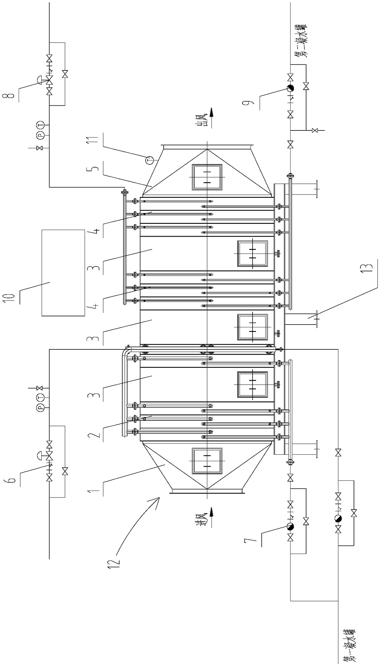
[0027] Such as figure 1 As shown, the steam-air preheater for controlling dioxin emission concentration includes a shell 12 , a first tube bundle 2 , a second tube bundle 4 , a temperature sensor 11 and a control cabinet 10 .
[0028] The housing 12 is hollow. The left end of the housing 12 is an air inlet, and the right end is an air outlet. Gas enters from the left end of the housing 12 and is discharged from the right end of the housing 12 . refer to figure 1 , the left end of the housing 12 is the air inlet pipe 1, and the right end is the air outlet pipe 5, the air inlet pipe 1 and the air outlet pipe 5 are respectively reducing pipes, wherein the air inlet pipe 1 becomes larger from left to right, and the outlet pipe 5 becomes larger. The air duct 5 becomes bigger successively from right to left. Further, the air inlet pipe 1 and the air outlet pipe 5 may have a symmetrical structure.
[0029] The cross section of the housing 12 can be square or circular.
[0030] Bo...
no. 2 example
[0043] The difference from the first embodiment is that there are two first tube bundles 2 .
[0044] Such as figure 1 As shown, the two first tube bundles 2 are respectively located on the left side of the second tube bundle 4 , and the two first tube bundles 2 are arranged along the axial direction of the casing 12 . Those skilled in the art can understand that the two first tube bundles 2 are internally connected, so that the steam passes through the two first tube bundles 2 in sequence to exchange heat for the gas passing through the casing 12 .
[0045]Each first tube bundle 2 has a pipe for discharging condensed water, and each pipe is provided with a first outlet valve group 7 for adjusting the amount of condensed water discharge, and the two pipes are finally connected to the first condensed water tank connect.
[0046] An inspection section 3 is arranged between the two first tube bundles 2 .
[0047] To sum up, by increasing the number of the first tube bundles 2 ...
no. 3 example
[0049] The difference from the first embodiment is that there are two second tube bundles 4 .
[0050] Such as figure 1 As shown, the two second tube bundles 4 are respectively located on the right side of the first tube bundle 2 , and the two second tube bundles 4 are arranged along the axial direction of the casing 12 . The two second tube bundles 4 are connected internally, so that steam can pass through the two second tube bundles 4 in sequence to exchange heat with the gas passing through the shell 12 .
[0051] An inspection section 3 is arranged between the two second tube bundles 4 .
[0052] To sum up, by increasing the number of the second tube bundle 4, the contact area between the second tube bundle 4 and the housing 12 is increased, that is, the contact area between the steam passing through the second tube bundle 4 and the gas passing through the housing 12 is increased, effectively improving the heat exchange efficiency , to avoid a large number of dioxins.
PUM
 Abstract
Description
Claims
Application Information
 - R&D
- Intellectual Property
- Life Sciences
- Materials
- Tech Scout
- Unparalleled Data Quality
- Higher Quality Content
- 60% Fewer Hallucinations
Browse by: Latest US Patents, China's latest patents, Technical Efficacy Thesaurus, Application Domain, Technology Topic, Popular Technical Reports.
© 2025 PatSnap. All rights reserved.Legal|Privacy policy|Modern Slavery Act Transparency Statement|Sitemap|About US| Contact US: help@patsnap.com

