
A method for testing the failure of a coupling

A technology for failure testing and couplings, which is applied in the testing of machines/structural components, machine gears/transmission mechanisms, and testing of mechanical components. The effect of melting and accurate detection

Active Publication Date: 2019-12-31
ANHUI JIANGHUAI AUTOMOBILE GRP CORP LTD
View PDF8 Cites 0 Cited by
  • Summary
  • Abstract
  • Description
  • Claims
  • Application Information

AI Technical Summary

Problems solved by technology

In the test project, the coupling failure will occur, which generally occurs in low-speed conditions. The main manifestation is that the damping rubber of the coupling is overheated, melted and broken, which may cause the engine to suddenly lose load, and overspeed will cause engine damage. Seriously, it will cause ACCIDENT
[0003] At present, the main detection method is temperature test, using a temperature sensor to detect the temperature of the shock-absorbing rubber; the temperature sensor can only measure the surface temperature of the shock-absorbing rubber, and due to the different structures of different types of couplings, some of the shock-absorbing rubber is directly exposed, Some are wrapped with iron sheets outside the vibration-damping rubber, and the temperature sensor cannot accurately measure the temperature of the vibration-damping rubber of the coupling
The coupling is a high-speed rotating part (800rpm-6000rpm), the temperature probe will rub against the surface of the coupling, and the temperature will rise, which will affect the measurement accuracy of the sensor; it is susceptible to heat radiation such as the water temperature, oil temperature, and exhaust temperature (1000°C) of the engine itself factors

Method used


Image

  • A method for testing the failure of a coupling
  • A method for testing the failure of a coupling
  • A method for testing the failure of a coupling

Examples


Embodiment Construction

[0056] Various exemplary embodiments of the present invention will now be described in detail with reference to the accompanying drawings. It should be noted that the relative arrangements of components and steps, numerical expressions and numerical values ​​set forth in these embodiments do not limit the scope of the present invention unless specifically stated otherwise.

[0057] The following description of at least one exemplary embodiment is merely illustrative in nature and in no way taken as limiting the invention, its application or uses.

[0058] Techniques, methods and devices known to those of ordinary skill in the relevant art may not be discussed in detail, but where appropriate, such techniques, methods and devices should be considered part of the description.

[0059] In all examples shown and discussed herein, any specific values ​​should be construed as exemplary only, and not as limitations. Therefore, other instances of the exemplary embodiment may have dif...


PUM


Abstract

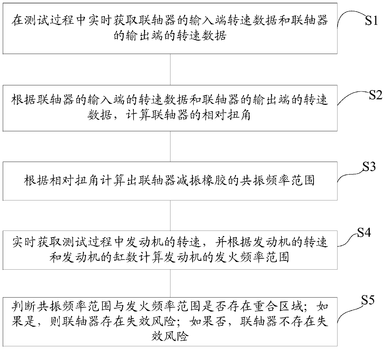
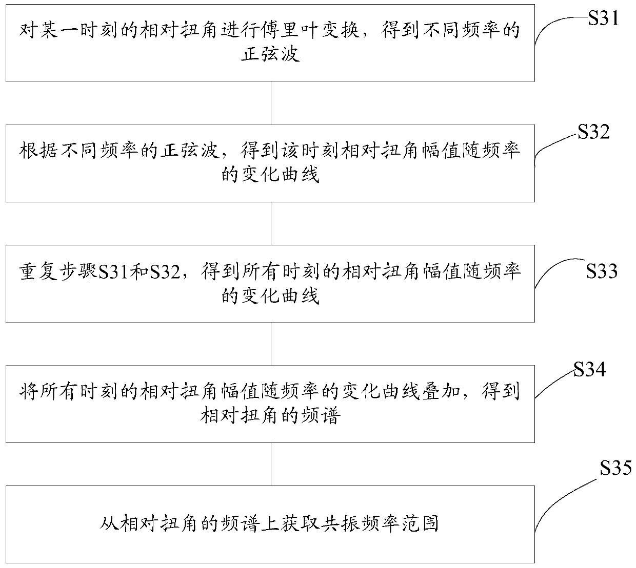
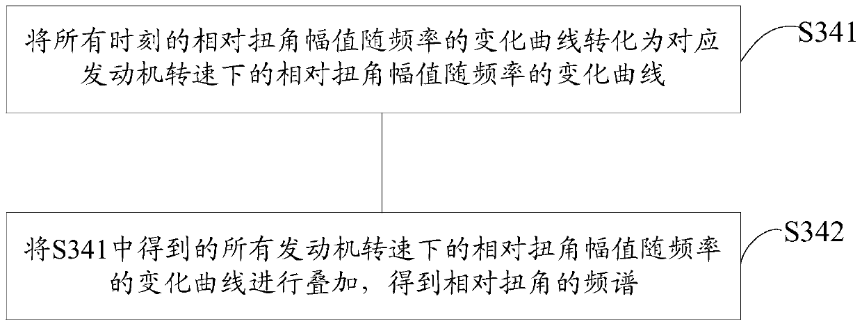
The invention discloses a failure testing method of a coupling device. The method comprises the steps that rotation rate data of an output end of the coupling device and rotation rate data of an inputend of the coupling device are obtained in real time in the testing process; a relative torsional angle of the coupling device is calculated according to the rotation rate data of the output end of the coupling device and the rotation rate data of the input end of the coupling device; resonance frequency range of shock-absorbing rubber of the coupling device is calculated according to the relative torsional angle; the rotation rate of an engine in the testing process is obtained in real time, and the firing frequency range of the engine is calculated according to the rotation rate and the cylinder number of the engine; whether or not there exists an overlapping region between the resonance frequency range and the firing frequency range, if yes, the failing risk of the coupling device exists, and if not, the failing risk of the coupling device does not exit. The method has the advantage that the failing risk of the coupling device can be conveniently and accurately detected.

Description

technical field [0001] The invention relates to the technical field of engine detection, in particular to a coupling failure testing method. Background technique [0002] During the engine test, it is necessary to use a coupling to connect the engine with the dynamometer to transmit power. By adjusting the load of the dynamometer and controlling the speed and torque of the engine, the engine can be controlled to achieve different test conditions. The vibration-absorbing rubber can absorb the speed fluctuations at both ends of the coupling for the purpose of buffering. At the same time, the length of the coupling can be adjusted through the cooperation of internal and external splines to meet the needs of different test benches. In the test project, the coupling failure will occur, which generally occurs in low-speed conditions. The main manifestation is that the damping rubber of the coupling is overheated, melted and broken, which may cause the engine to suddenly lose load...

Claims


Application Information

Patent Timeline
Patent Type & Authority Patents(China)
IPC IPC(8): G01M13/02
CPCG01M13/022
Inventor 赵帅钱多德陈玮范习民王金立李凯孙邦江王国刚袁飞王卓谢素萍高冬冬吕勤
Owner ANHUI JIANGHUAI AUTOMOBILE GRP CORP LTD
Learn More