
Method for controlling power dissipation and terminal equipment

A technology of terminal equipment and power consumption, which is applied in the directions of electromagnetic wave re-radiation, image data processing, and utilization of re-radiation, etc. It can solve the problems that cannot meet the needs of different scenarios

Inactive Publication Date: 2019-03-15
VIVO MOBILE COMM CO LTD
View PDF6 Cites 3 Cited by
  • Summary
  • Abstract
  • Description
  • Claims
  • Application Information

AI Technical Summary

Problems solved by technology

[0005] Embodiments of the present invention provide a method for controlling power consumption and a terminal device, so as to solve the problem in the prior art that the method of transmitting pulsed optical signals with a fixed pulse width cannot meet the use requirements of different scenarios

Method used


Image

  • Method for controlling power dissipation and terminal equipment
  • Method for controlling power dissipation and terminal equipment
  • Method for controlling power dissipation and terminal equipment

Examples


Embodiment Construction

[0018] The following will clearly and completely describe the technical solutions in the embodiments of the present invention with reference to the accompanying drawings in the embodiments of the present invention. Obviously, the described embodiments are some of the embodiments of the present invention, but not all of them. Based on the embodiments of the present invention, all other embodiments obtained by persons of ordinary skill in the art without creative efforts fall within the protection scope of the present invention.

[0019] It should be noted that " / " in this article means or, for example, A / B can mean A or B; "and / or" in this article is just an association relationship describing associated objects, indicating that there can be three A relationship, for example, A and / or B, can mean: A exists alone, A and B exist simultaneously, and B exists alone. "A plurality" means two or more than two.

[0020] The terms "first" and "second" in the specification and claims of...


PUM


Abstract

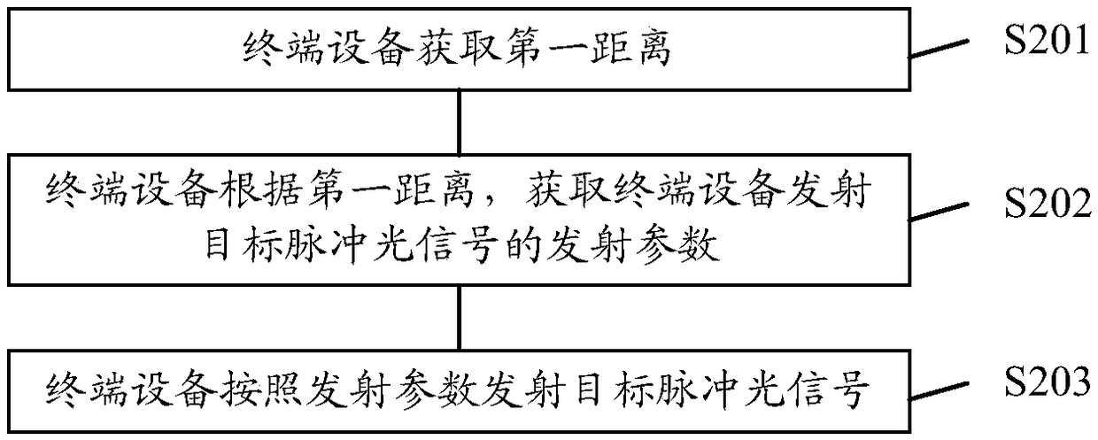
The embodiment of the invention provides a method for controlling power dissipation and terminal equipment, and relates to the technical field of communication. The problem in the prior art that a mode of adopting fixed pulse width for emitting pulse light signals cannot meet the using requirements of different scenes is solved. The method comprises the steps of obtaining a first distance, whereinthe first distance is the distance between the terminal equipment and a target object; obtaining emitting parameters for emitting target pulse light signals of the terminal equipment according to thefirst distance; emitting the target pulse light signals according to the emitting parameters, wherein the emitting parameters include the target pulse width, or include the target pulse width and target pulse strength, the target pulse width is the emitting time for emitting a single pulse light signal, and the target pulse strength is signal strength of the single emitted pulse light signal.

Description

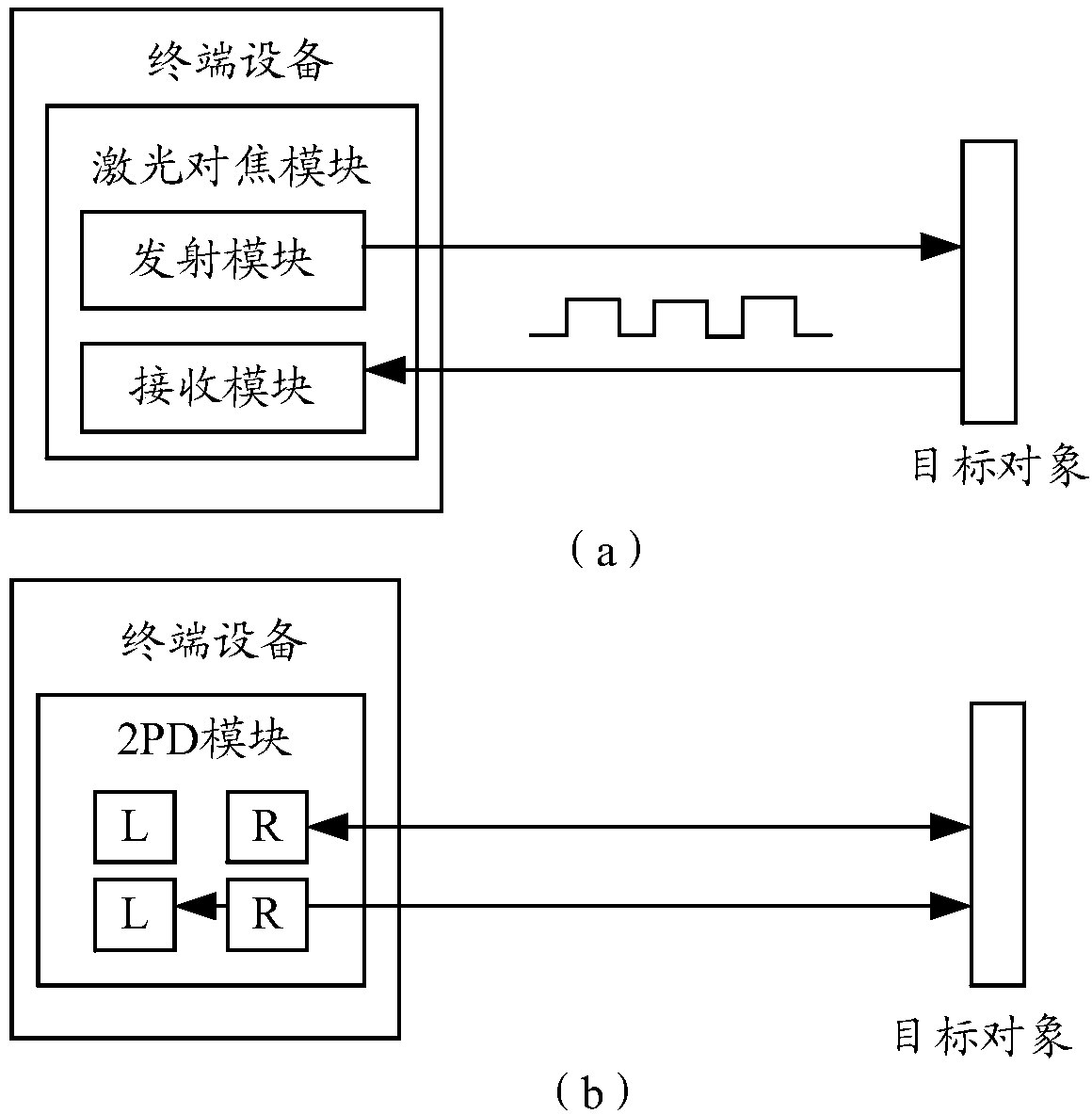
technical field [0001] Embodiments of the present invention relate to the field of communication technologies, and in particular, to a method for controlling power consumption and a terminal device. Background technique [0002] At present, the time of flight (time of flight, TOF) technology is more and more widely used. For example, the terminal device may use the TOF module in the terminal device to perform three-dimensional (three dimensions, 3D) modeling, synthesize 3D images, distance detection or face recognition, and the like. [0003] Generally, when a terminal device uses a TOF module, it can send pulsed optical signals to the object under test at different time slots through the vertical cavity surface emitting laser (VCSEL) in the TOF module, and the terminal device can transmit pulsed optical signals according to the reflection of the object under test. The returned optical signal measures the depth of field information. Wherein, the pulse width of the pulsed o...

Claims


Application Information

Patent Timeline
IPC IPC(8): G01S17/10G06T7/521
CPCG01S17/10G06T7/521
Inventor 刘林
Owner VIVO MOBILE COMM CO LTD
Learn More