
Blower

A blower and fan technology, applied in ventilation systems, mechanical equipment, machines/engines, etc., can solve problems such as manual adjustment of up and down directions, discomfort, dust or foreign matter accumulation, etc.

Active Publication Date: 2019-03-15
LG ELECTRONICS INC
View PDF7 Cites 2 Cited by
  • Summary
  • Abstract
  • Description
  • Claims
  • Application Information

AI Technical Summary

Problems solved by technology

[0012] First, there is the inconvenience that the user needs to arbitrarily change the position of the main body in order to adjust the direction of the wind blown from the fan blade in the vertical direction.
That is, there is a problem that the user needs to manually adjust the up and down direction
[0013] Second, even if the user manually adjusts the up and down directions, there is still the problem of only sending air to one side
That is, although the existing air blower can automatically reciprocate in the left and right directions, it cannot reciprocate in the up and down direction, so there is inconvenience that the user needs to adjust the direction arbitrarily.
[0014] Third, the first safety cover and the second safety cover that are usually used to configure the fan blade are formed in a grid shape, so there is a problem that fine dust or foreign matter in the external air will accumulate on the fan blade as it is used
Therefore, there is a problem that the user feels uncomfortable due to dust when using the air blower.

Method used


Image

  • Blower
  • Blower
  • Blower

Examples


Embodiment Construction

[0072] Hereinafter, embodiments of the present invention will be described in detail with reference to the accompanying drawings, so that those skilled in the art of the present invention can easily implement the present invention. The present invention can be realized in many different forms, and is not limited to the structures or methods described here.

[0073] In addition, terms such as first, second, A, B, a, b, etc. may be used in describing constituent elements of the embodiments of the present invention. Such terms are used only to distinguish the constituent elements from other constituent elements, and the nature or sequence / sequence of the constituent elements will not be limited by the term.

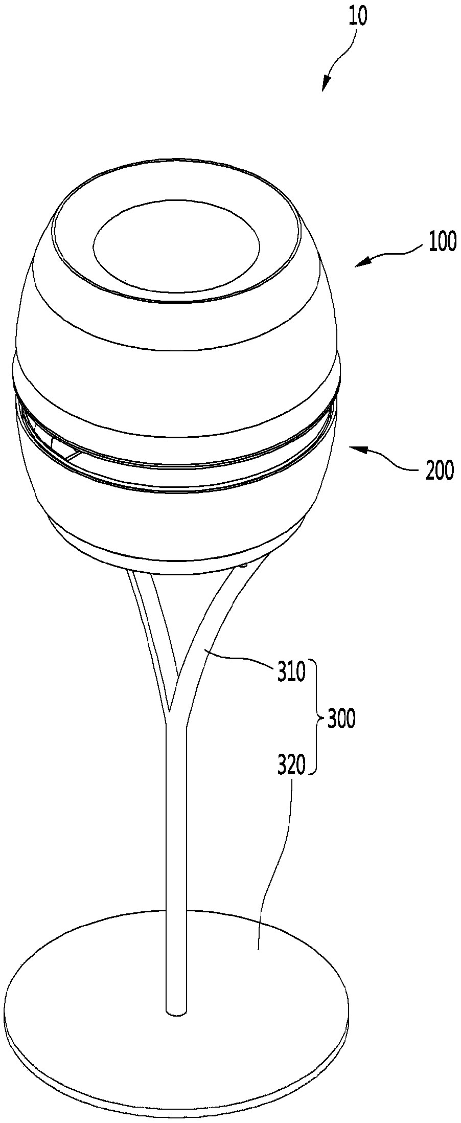
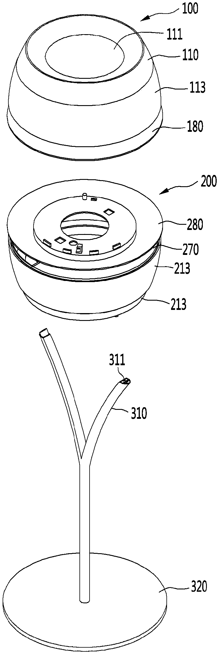
[0074] figure 1 is a perspective view of an air blower according to an embodiment of the present invention, figure 2 It is an exploded view of the blower according to the embodiment of the present invention.

[0075] refer to figure 1 and figure 2 In other words, the ...


PUM


Abstract

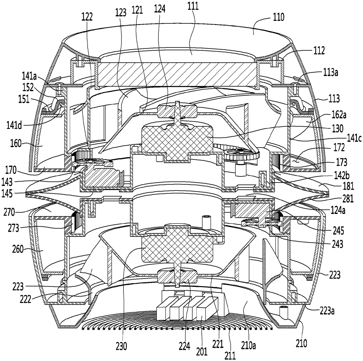
The present invention relates to a blower. A blower according to one embodiment of the present invention comprises: an upper fan for generating a first airflow, which is suctioned through an upper suction part and is then discharged; a lower fan disposed under the upper fan to generate a second airflow, which is suctioned through a lower suction part and is then discharged; an airflow changing device disposed between the upper fan and the lower fan to generate a third airflow by joining the first airflow and the second airflow; and a control part for controlling the rotation speed of each of the upper fan and the lower fan to adjust the discharge direction of the third airflow.

Description

technical field [0001] The present invention relates to blowers. Background technique [0002] Generally, a blower is understood as a device for sucking in air and blowing it to the desired location of the user. Such air blowers are mainly arranged in indoor spaces such as residences or offices, and most of them are activated in hot weather like summer to blow air to users, making users feel cool. [0003] Existing air blowers usually consist of a support rod and a blowing part. The existing literature on such prior blowers is as follows. [0004] prior art literature [0005] patent documents [0006] Publication Patent Publication No. 10-2008-0087365 (Date of Publication: October 1, 2008, Name of Invention: Fan) [0007] The structure of the existing air blower mentioned in the published prior art documents includes: a body with a built-in motor; a fan blade part, which is arranged on the body and combined with the motor, and can rotate with the operation of the motor...

Claims


Application Information

Patent Timeline
IPC IPC(8): F04D25/08F04D27/02F04D29/30F04D29/40F04D25/06F04D29/00
CPCF04D17/162F04D25/08F04D25/10F04D25/166F04D29/424F24F7/007F04D25/06F04D27/02F04D29/002F04D29/30F04D29/403F04D27/004F04D29/281F24F1/0014
Inventor 具命辰朴熙哲
Owner LG ELECTRONICS INC
Learn More