Lateral components, chain links and energy guiding chains

A technology for energy guiding chains and components, applied to lateral components, can solve problems such as mutual collision, and achieve the effects of reducing residual speed, protecting materials, and receiving more

Active Publication Date: 2021-03-09
IGUS
View PDF3 Cites 0 Cited by
  • Summary
  • Abstract
  • Description
  • Claims
  • Application Information

AI Technical Summary

Problems solved by technology

[0005] However, if at the same time a certain damping is thereby achieved in each case, an excess remains of a defined residual velocity at which the stop surfaces suddenly collide with each other with the formation of unwanted noises.

Method used


Image

  • Lateral components, chain links and energy guiding chains
  • Lateral components, chain links and energy guiding chains
  • Lateral components, chain links and energy guiding chains

Examples


Embodiment Construction

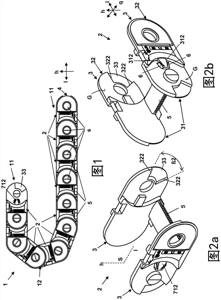
[0052] (In the specification, all concepts used to describe directionality such as up, down, front, back, right, and left refer to the directions shown in the corresponding drawings, which may actually be defined differently) figure 1 shows a side view of an energy guide chain 1 with the chain links 2 shown in FIGS. In this case, all pivot axes s are arranged in the energy guide chain 1 in the transverse direction q and thus parallel to one another. In this case, the energy guide chain 1 is generally displaceable with two straight segments 11 being formed by a deflection segment 12 , wherein the chain links 2 are each opposite each other when transitioning from a straight segment 11 to the deflection segment 12 pivot.

[0053] The chain links 2 each have two lateral parts 3 which, in the assembled state inserted into the energy guide chain, form a left-hand and a right-hand tongue chain 4 . In this case, in this embodiment of the energy guide chain 1 , the two lateral parts ...


PUM


Abstract

The invention relates to a lateral part (3) for designing a chain link (2) of an energy guide chain (1) for guiding a supply line. For the pivotable arrangement of adjacent chain links (2), the side parts (3) each have a corresponding stop surface (312, 322) and a pivot axis (s ), that is, a first overlapping region (31) having a first stop surface (312) and a second overlapping region (32) having a second stop surface (322). In order to damp the braking of the pivoting movement, a spring lip (6) is arranged upstream of at least each first stop surface (312) in the form of a spring elastically deformable about a bending axis (b) parallel to the pivoting axis (s). ) form of damping elements. For improved damping it is provided that the spring lip (6) has an axial end region (61) with respect to its bending axis (b) for coupling in kinetic energy which is passed through adjacent chain links A second stop surface ( 322 ) of the second overlapping region ( 32 ) of ( 2 ), which in the assembled state corresponds to the first stop surface ( 312 ), is transferred to the spring lip ( 6 ).

Description

technical field [0001] The invention relates to a lateral part for designing chain links of an energy guide chain for guiding supply lines, wherein adjacent chain links are pivotally connected relative to each other about a pivot axis, wherein for adjacent The pivotable arrangement of the chain links, the lateral parts on the end sides respectively have overlapping areas provided with corresponding stop surfaces and pivot axes in order to limit the pivoting, that is to say the first intersection with the first stop surface and a second overlapping area with a second stop surface, and, in order to damp the braking of the pivotal movement, a damping element is arranged upstream of at least each first stop surface, which is arranged around a parallel In the form of a spring lip that deforms elastically with respect to the bending axis of the pivot axis. The invention also relates to a chain link with two such lateral parts and an energy guide chain with such a chain link. Back...

Claims


Application Information

Patent Timeline
Patent Type & Authority Patents(China)
IPC IPC(8): F16G13/16
CPCF16G13/16
Inventor J·多姆尼克A·赫尔迈
Owner IGUS
Why Eureka
Try Eureka