Power control method, device, terminal and network equipment
A technology of network equipment and power control, which is applied in the field of wireless communication and can solve the problem of untargeted transmission power
- Summary
- Abstract
- Description
- Claims
- Application Information
AI Technical Summary
Problems solved by technology
Method used
Image
Examples
Embodiment 1
[0066] Please refer to image 3 , which shows a flowchart of a power control method provided by an embodiment of the present invention. The method may include the following steps.
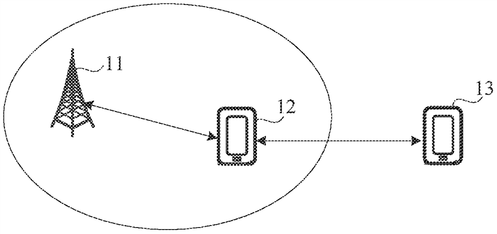
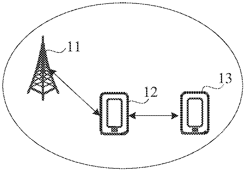
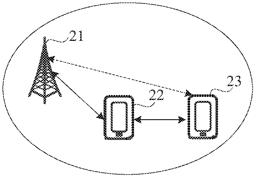
[0067] Step 301, the first terminal acquires power control information, where the power control information is information used to control the transmit power of the first terminal when communicating with the second terminal.
[0068] Wherein, a first communication link is established between the first terminal and the second terminal.
[0069] Power control information includes the following possible implementations:
[0070] 1. The power control information includes the transmit power used by the first terminal when communicating with the second terminal.
[0071] In an example, the adopted transmit power is determined by the second terminal. Optionally, the adopted transmit power is determined by the second terminal according to a received power value, where the received power value is a powe...
Embodiment 2
[0090] Please refer to Figure 4 , which shows a flowchart of a power control method provided by another embodiment of the present invention. The method may include the following steps.
[0091] In step 401, the network device determines power control information, where the power control information is information used to control the transmit power of the first terminal when communicating with the second terminal.
[0092] Wherein, a first communication link is established between the first terminal and the second terminal.
[0093] Power control information includes the following possible implementations:
[0094] 1. The power control information includes the transmit power used by the first terminal when communicating with the second terminal.
[0095] Wherein, the adopted transmit power is determined by the network device according to the received power value, which is the power value of the signal sent by the first terminal on the first communication link received by th...
Embodiment 3
[0108] Please refer to Figure 5 , which shows a flowchart of a power control method provided by another embodiment of the present invention. The method may include the following steps.
[0109] Step 501, the second terminal determines power control information, where the power control information is information used to control the transmit power of the first terminal when communicating with the second terminal.
[0110] Wherein, a first communication link is established between the first terminal and the second terminal.
[0111] Power control information includes the following possible implementations:
[0112] 1. The power control information includes the transmit power used by the first terminal when communicating with the second terminal.
[0113] Optionally, the adopted transmit power is determined by the second terminal according to a received power value, where the received power value is a power value received by the second terminal or network equipment of a signal s...
PUM
 Abstract
Description
Claims
Application Information
 - R&D
- Intellectual Property
- Life Sciences
- Materials
- Tech Scout
- Unparalleled Data Quality
- Higher Quality Content
- 60% Fewer Hallucinations
Browse by: Latest US Patents, China's latest patents, Technical Efficacy Thesaurus, Application Domain, Technology Topic, Popular Technical Reports.
© 2025 PatSnap. All rights reserved.Legal|Privacy policy|Modern Slavery Act Transparency Statement|Sitemap|About US| Contact US: help@patsnap.com


