Building component japanning device

A technology of building components and mounting seats, which is applied in the direction of spraying devices, etc., can solve the problems of uneven painting effect, unstable painting effect, and inability to paint, etc., to achieve stable driving and uniform speed, uniform and stable painting effect, Stable effect in the varnishing process

Inactive Publication Date: 2019-03-19
NANYANG LINGYU MACHINERY CO LTD
View PDF8 Cites 3 Cited by
  • Summary
  • Abstract
  • Description
  • Claims
  • Application Information

AI Technical Summary

Problems solved by technology

The current steel will be coated with a layer of paint on the surface of the steel during processing, which can effectively prevent the outer surface of the steel from rusting and corrosion. When the steel is used, the painting effect is unstable, and the steel cannot be painted evenly, which will cause local corrosion of the steel
Moreover, there are irregularly shaped steel materials, which may not be able to be partially painted due to the irregular shape during the painting process; therefore, it is necessary to provide a paint for building components with stable paint effect, wide paint range and uniform paint device is very necessary

Method used


Image

  • Building component japanning device
  • Building component japanning device
  • Building component japanning device

Examples


Embodiment 1

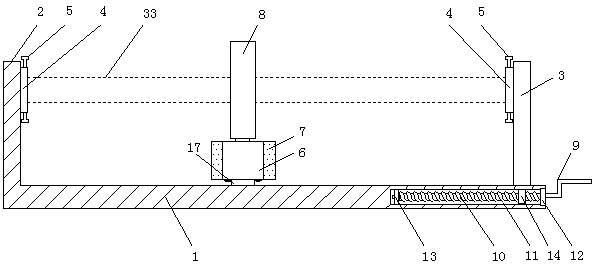
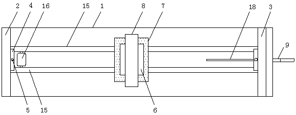
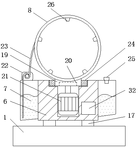
[0023] like Figure 1-8 As shown, the painting device for building components includes a base 1, the left side of the base 1 is provided with a fixed plate 2, the right side of the base 1 is provided with a movable plate 3, and the center of the bottom of the movable plate 3 is provided with a nut 14, Described nut 14 cooperates with screw mandrel 10, and described screw mandrel 10 is fixed in cylindrical groove 11 by front bearing 12 and rear bearing 13 respectively, and the outside of described front bearing 12 is provided with the handle 9 that is fixedly connected with screw mandrel 10 , the upper part of the cylindrical groove 11 is provided with a rectangular groove 18 for the nut 14 to move, the fixed plate 2 and the movable plate 3 are provided with a fixed ring 4, and the top and bottom of the fixed 4 rings are provided with fastening rings. Bolt 5, the lower part of the fastening bolt 5 is provided with an arc-shaped pressure plate 28, the upper part of the base 1 is...

Embodiment 2

[0026] like Figure 1-8 As shown, the painting device for building components includes a base 1, the left side of the base 1 is provided with a fixed plate 2, the right side of the base 1 is provided with a movable plate 3, and the center of the bottom of the movable plate 3 is provided with a nut 14, Described nut 14 cooperates with screw mandrel 10, and described screw mandrel 10 is fixed in cylindrical groove 11 by front bearing 12 and rear bearing 13 respectively, and the outside of described front bearing 12 is provided with the handle 9 that is fixedly connected with screw mandrel 10 , the upper part of the cylindrical groove 11 is provided with a rectangular groove 18 for the nut 14 to move, the fixed plate 2 and the movable plate 3 are provided with a fixed ring 4, and the top and bottom of the fixed 4 rings are provided with fastening rings. Bolt 5, the lower part of the fastening bolt 5 is provided with an arc-shaped pressure plate 28, the upper part of the base 1 is...


PUM


Abstract

The invention relates to a building component japanning device. The building component japanning device comprises a base. A fixed plate is arranged on the left side of the base. A movable plate is arranged on the right side of the base. The fixed plate and the movable plate are both provided with fixed rings. The top and bottom of each fixed ring are provided with fastening bolts. A mounting baseis arranged above the base. A motor B is fixedly mounted in the mounting base. An external gear is arranged at the rotary output end of the upper portion of the motor B. The external gear is engaged with an internal gear. The internal gear is arranged on a rotary part. A japanning device body is fixedly arranged on the upper portion of the rotary part. The inner side of the japanning device body is provided with a paint spray gun head. The rotary part is fixed to the upper portion of the mounting base through a bearing A. A paint storage tank is arranged on the outer side of the mounting base.A booster pump and a tank plug are arranged on the upper portion of the paint storage tank. The booster pump is connected with the paint spray gun head of the japanning device body through a guide pipe. The lower end of the guide pipe is arranged n the paint storage tank. Sliding blocks are arranged at the bottom of the mounting base. The sliding blocks are arranged on electric sliding rails. Thebuilding component japanning device has the advantages of being stable in japanning effect, wide in japanning range and uniform in japanning.

Description

technical field [0001] The invention relates to the technical field of building equipment processing, in particular to a painting device for building components. Background technique [0002] At present, the main structure of many buildings is composed of a large number of steel structural parts. The steel structural parts have high strength, high overall rigidity, strong deformation capacity and heavy load. The current steel will be coated with a layer of paint on the surface of the steel during processing, which can effectively prevent the outer surface of the steel from rusting and corrosion. When the steel is used, the painting effect is unstable, and the steel cannot be painted evenly, which will cause local corrosion of the steel. Moreover, there are irregularly shaped steel materials, which may not be able to be partially painted due to the irregular shape during the painting process; therefore, it is necessary to provide a paint for building components with stable p...

Claims


Application Information

Patent Timeline
Patent Type & Authority Applications(China)
IPC IPC(8): B05B13/02B05B13/04
CPCB05B13/0285B05B13/041B05B13/0426
Inventor 王飞孙伟郭娇龙杨喜锋包冬旭杨喜景张春祥
Owner NANYANG LINGYU MACHINERY CO LTD
Why Eureka
Try Eureka