
Water barrier

A fence and main body technology, applied in the field of water conservancy engineering, can solve the problems of large material consumption, waste of resources, heavy quality, etc., and achieve the effect of simple and convenient operation and lowering of the lifting force.

Active Publication Date: 2020-08-25
东阳市善水环境工程有限公司
View PDF4 Cites 0 Cited by
  • Summary
  • Abstract
  • Description
  • Claims
  • Application Information

AI Technical Summary

Problems solved by technology

[0002] The existing dams have the problems of long construction time, high construction difficulty, and large material and energy consumption during the construction process.
Specifically reflected in: 1. When building a dam, a large amount of concrete or earth and stone needs to be used, the material consumption is large, the construction time is several years or decades, and the construction is difficult; 2. Commonly used in dams The gate is made of concrete or steel plate. Generally, when the gate is opened, it is opened by an elevator. Due to the large size and heavy weight of the gate plate, the elevator needs to use a large lifting force during the lifting process, which wastes resources. At the same time, the front end of the gate Or a fence needs to be set up in the downstream to isolate the floating objects in the water. Therefore, the setting of the two structures leads to complex construction on site, high labor intensity, and affects the aesthetics of the river.

Method used


Image

  • Water barrier
  • Water barrier

Examples


Embodiment Construction

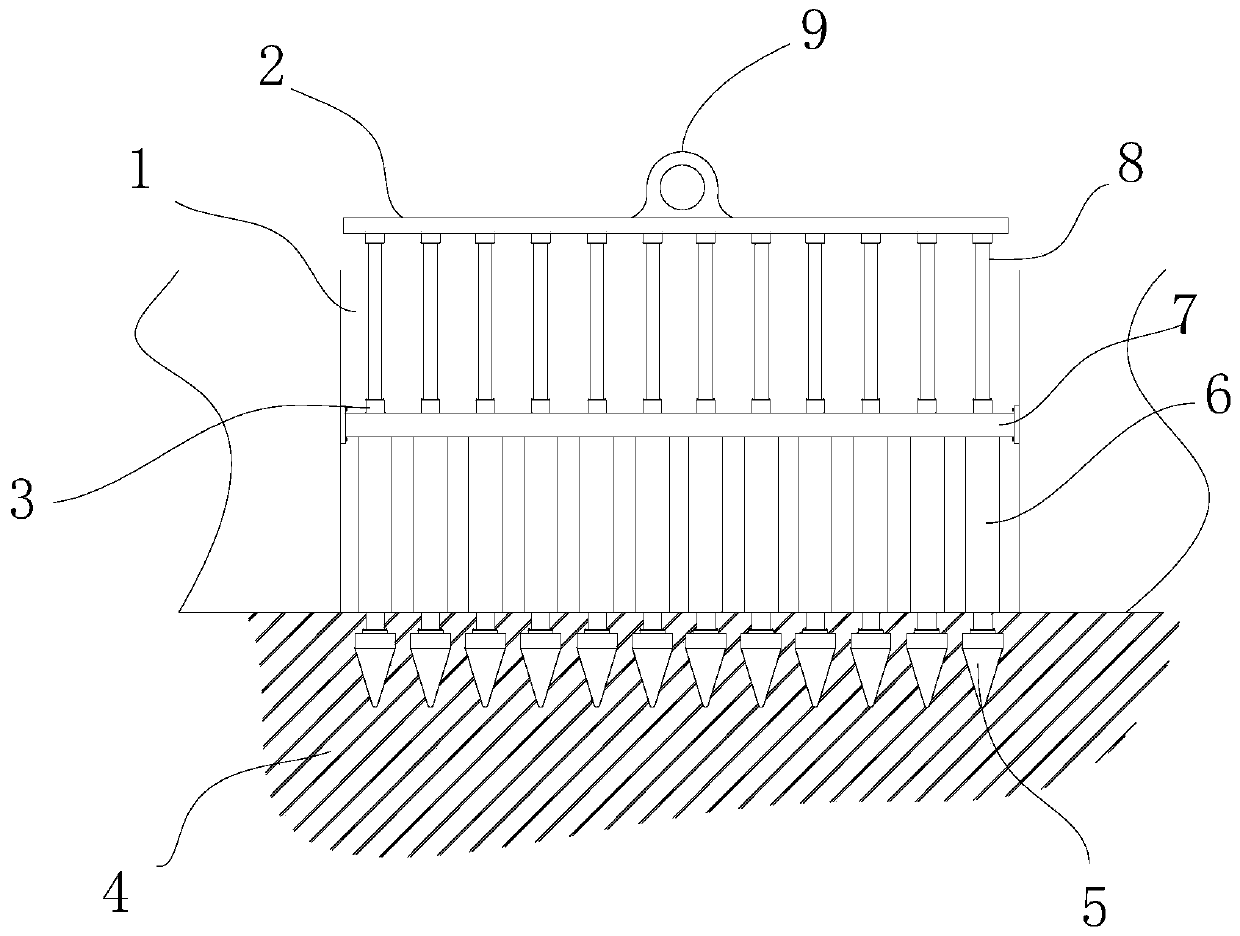
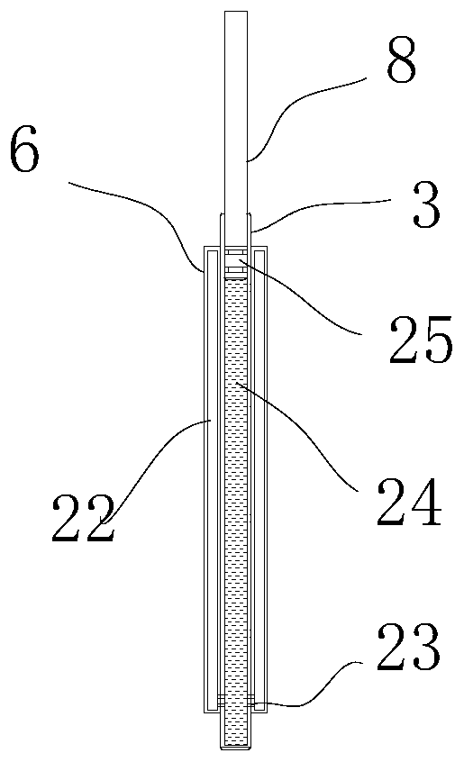
[0014] Such as figure 1 and figure 2 As shown, the water retaining fence includes a fence installed at the drainage gate 1, the fence includes a fence body and a lifting device installed on the top of the fence body, the fence body includes a cross bar 7 installed at the drainage gate 1, and the cross bar Insert more than one positioning plunger 3 equidistantly in 7 from top to bottom, and a ground insert 5 is arranged at the bottom of the positioning plunger 3, and the ground insert 5 is inserted in the river bed and fixed by pouring concrete material 4, and the positioning plunger 3 The top of the top protrudes from the upper end surface of the cross bar 7, and a drainage chamber is formed between the cross bar 7 and the upper end surface of the concrete material 4, and the positioning insert rod 3 located in the drainage chamber is wrapped with a layer of elastic sealing column 6 outside, and the elastic seal A gap cavity for water supply and discharge is formed between t...


PUM


Abstract

The invention discloses a water retaining fence, which includes a fence body installed at a drainage gate opening. The fence includes a fence body and a lifting pulling device installed at the top ofthe fence body, the fence body includes a cross rod installed at the drainage gate opening, one or more positioning inserting rods are inserted into the cross rod at equal distance from top to bottom,and ground inserting pieces are arranged at the bottoms of the positioning inserting rods correspondingly; the ground inserting pieces are inserted into a riverbed and fixed by concrete pouring, andthe tops of the positioning inserting rods extend out of the upper end face of the cross rod; and a drainage cavity is formed between the cross bar and the upper end face of a concrete material, the positioning inserting rods located in the drainage cavity are externally wrapped with layers of elastic sealing columns correspondingly, gap cavities allowing water to discharge are formed between theelastic sealing columns, and the elastic seal columns are expanded or contracted by pressing the lifting pulling device downwards. The fence is installed at the gate opening to act as a gate, and canintercept floating objects; and lifting force of gate plate lifting is lowered, and operation is simpler and more convenient.

Description

technical field [0001] The invention relates to the field of water conservancy engineering, in particular to a water blocking fence. Background technique [0002] The existing dams have the problems of long construction time, high construction difficulty, and large material and energy consumption during the construction process. Specifically reflected in: 1. When building a dam, a large amount of concrete or earth and stone needs to be used, the material consumption is large, the construction time is several years or decades, and the construction is difficult; 2. Commonly used in dams The gate is made of concrete or steel plate. Generally, when the gate is opened, it is opened by an elevator. Due to the large size and heavy weight of the gate plate, the elevator needs to use a large lifting force during the lifting process, which wastes resources. At the same time, the front end of the gate Or a fence needs to be set up in the downstream to isolate the floating objects in t...

Claims


Application Information

Patent Timeline
Patent Type & Authority Patents(China)
IPC IPC(8): E02B15/06E02B8/02E02B7/24
CPCE02B7/24E02B8/023E02B15/06
Inventor 陈茂清
Owner 东阳市善水环境工程有限公司
Learn More