Power clutch system and executing mechanism

An actuator and power technology, applied in the field of power clutch systems and actuators, can solve problems such as lack of self-locking function, low efficiency of work, and increased heat dissipation of the transmission

Inactive Publication Date: 2019-03-19
SCHAEFFLER TECH AG & CO KG
View PDF0 Cites 1 Cited by
  • Summary
  • Abstract
  • Description
  • Claims
  • Application Information

AI Technical Summary

Problems solved by technology

[0004] At present, the actuators of these power clutch mechanisms either do not have the self-locking function, or the execution stroke is uncontrollable, or there are some problems that the heat dissipation of the transmission increases due to low efficiency and waits for improvement.

Method used


Image

  • Power clutch system and executing mechanism
  • Power clutch system and executing mechanism
  • Power clutch system and executing mechanism

Examples


Embodiment Construction

[0037] It can be seen from the background technology that the execution function of the current actuator needs to be improved. The following is a concrete analysis of the reasons for an executive mechanism.

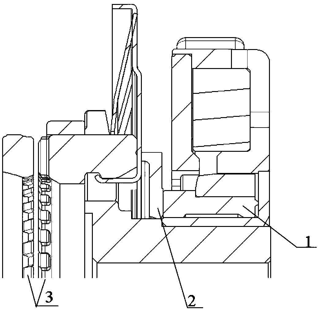
[0038] figure 1 It is a sectional view of an actuator.

[0039] Such as figure 1 As shown, the actuator includes a push rod 2, a moving part and a diaphragm spring. When the circuit is connected, the electromagnetic clutch 1 pushes the push rod 2 to move forward, the push rod 2 acts on the diaphragm spring, and the diaphragm spring acts on the moving part , the moving part acts on the gear 3, and the final result is that the two gears 3 are meshed, so that the power can be transmitted.

[0040] It can be seen that in order to maintain the state of the two gears 3 meshing with each other, the diaphragm spring must always act on the moving part, that is, the circuit must always be turned on, otherwise the moving part will be unable to provide the force acting on the diap...


PUM


Abstract

The invention discloses a power clutch system and an executing mechanism. The executing mechanism comprises a fixed part and a moving part, wherein the fixed part comprises a fixed part threaded portion, first threads are arranged on the fixed part threaded portion, the moving part comprises a moving part threaded portion, second threads are arranged on the moving part threaded portion, the fixedpart threaded portion and the moving part threaded portion are in threaded connection through the first threads and the second threads, and the moving part is driven by a power source to do linear motion relative to the fixed part based on the threaded connection so as to change the state of the power clutch mechanism. The executing mechanism plays a self-locking function, and the moving part canbe prevented from resetting under the condition that the power source is cut off; and furthermore, the executing mechanism has an axial distance adjustable function.

Description

technical field [0001] The embodiments of the present invention relate to the technical field of automobiles, in particular to a power clutch system and an actuator. Background technique [0002] At present, the power clutch mechanism that is widely used to realize power transmission or cut off is a friction clutch with spring compression. The torque generated by the engine is transmitted to the driven disc through the friction between the flywheel and the contact surface between the pressure plate and the driven disc. When the driver depresses the clutch pedal, the large end of the diaphragm spring drives the pressure plate to move backward through the transmission of the mechanical parts. At this time, the driven part is separated from the driving part, and the power transmission is cut off. [0003] In the currently developed power solutions for a class of new energy electric vehicles, the transmission needs to have a power cut-off function during power transmission. Th...

Claims


Application Information

Patent Timeline
Patent Type & Authority Applications(China)
IPC IPC(8): F16D11/16H02K7/116
CPCF16D11/16H02K7/116
Inventor 李清泉韦随心
Owner SCHAEFFLER TECH AG & CO KG
Why Eureka
Try Eureka