Three-shaft holder mechanism

A technology of pan/tilt and mandrel, which is applied in the directions of supporting machines, mechanical equipment, machine/stands, etc., and can solve problems such as the inability to adjust the angle and position of the signal transmitting device or the signal receiving device, and the single-axis rotation of the pan/tilt mechanism.

Pending Publication Date: 2019-03-19
CHONGQING DIMA IND
View PDF6 Cites 2 Cited by
  • Summary
  • Abstract
  • Description
  • Claims
  • Application Information

AI Technical Summary

Problems solved by technology

[0003] The object of the present invention is to overcome the problem that the pan-tilt mechanism in the prior art rotates on one axis and cannot adjust the angle and position of some signal transmitting devices or signal receiving devices, and provides a three-axis pan-tilt mechanism that can control the signal transmission Fully adjust the angle and position of the device or signal receiving device

Method used


Image

  • Three-shaft holder mechanism
  • Three-shaft holder mechanism

Examples


Embodiment Construction

[0019] The present invention will be further described in detail below in conjunction with test examples and specific embodiments. However, it should not be understood that the scope of the above subject matter of the present invention is limited to the following embodiments, and all technologies realized based on the content of the present invention belong to the scope of the present invention.

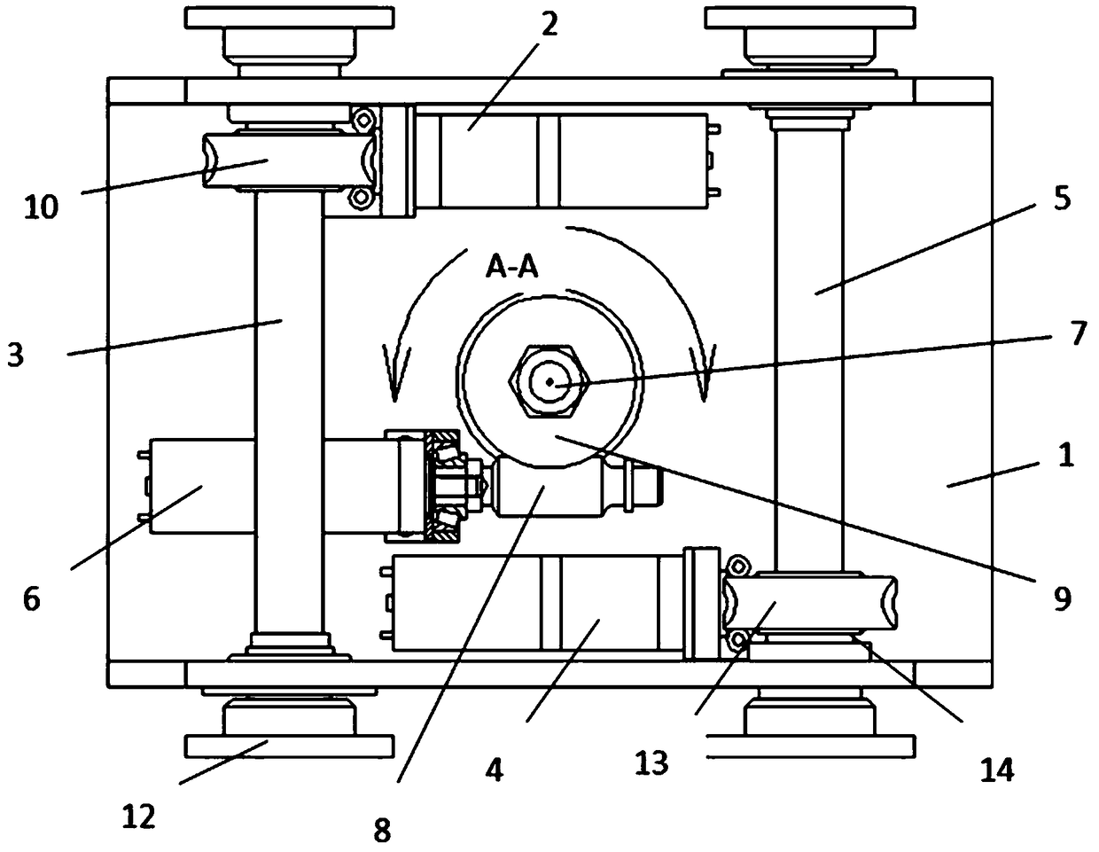
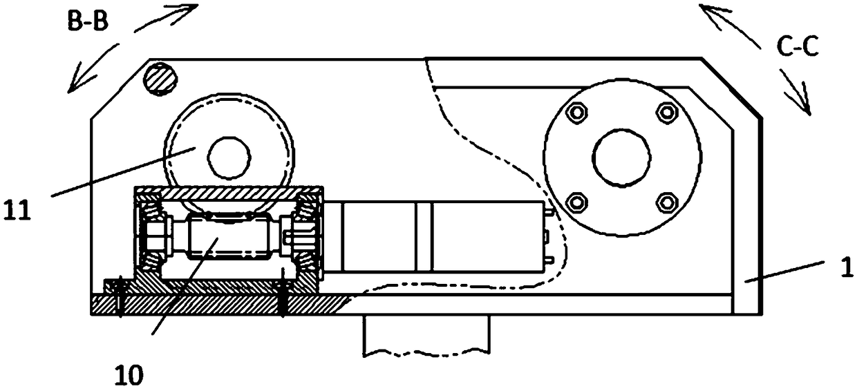
[0020] Such as Figure 1-2 , a three-axis pan-tilt mechanism, including a box body 1, a first motor 2, a first pitch axis 3, a second motor 4, a second pitch axis 5, a third motor 6 and a core shaft 7; the first motor 2 is fixed On the box body 1, a first worm 10 is arranged on the output shaft of the first motor 2, the two ends of the first worm 10 are rotatably supported on the bracket, and the two ends of the first pitch axis 3 are mounted on the box body with bearings On the two walls of 1, the first turbine 11 arranged on the first pitch shaft 3 is in transmission cooperation w...


PUM


Abstract

The invention discloses a three-shaft holder mechanism. A first motor is fixed on a box body; a first worm rod is arranged on an output shaft of the first motor; a first pitching shaft is rotationallyerected on two walls of the box body; a first turbine arranged on the first pitching shaft is in transmission fit with the first worm rod; connecting discs are arranged at two ends of the first pitching shaft, and are positioned at the external of the box body; a second motor is fixed on the box body; a second worm rod is arranged on an output shaft of the second motor; a second pitching shaft isrotationally erected on two walls of the box body; a second turbine arranged on the second pitching shaft is in transmission fit with the second worm rod; connecting discs are arranged at two ends ofthe second pitching shaft, and are positioned at the external of the box body; a mandrel penetrates through the bottom of the box body, and is connected with the bottom of the box body; the box bodycan be rotated around the mandrel; a third motor is fixed on the box body; a third worm rod is arranged on an output shaft of the third motor; a third turbine is fixed on the mandrel; and the third worm rod and the third turbine are in transmission fit.

Description

technical field [0001] The invention relates to a pan-tilt mechanism, in particular to a three-axis pan-tilt mechanism. Background technique [0002] With the development of the communication industry, the coverage of communication signals is getting wider and wider. However, there are still some places where there is no communication signal, or the communication signal is very weak. Now a mobile communication vehicle appears, which is equivalent to a mobile base station. It can Fill the places where there is no communication signal or the signal is very weak to ensure normal communication. The top of this mobile base station is generally equipped with a pan-tilt mechanism. The function of the pan-tilt mechanism is to support the signal transmitting device or signal receiving device. The angle and position of the signal transmitting device or signal receiving device can be adjusted through the rotation or lifting movement of the pan-tilt mechanism. , to ensure that the comm...

Claims


Application Information

Patent Timeline
Patent Type & Authority Applications(China)
IPC IPC(8): F16M11/12F16M11/22B60R11/02
CPCF16M11/121F16M11/22B60R11/02
Inventor 刘刚刘达平张聪波曾晓刚朱长虹吴志军陈扬胥成沛
Owner CHONGQING DIMA IND
Why Eureka
Try Eureka