A kind of LED light that can be used in multiple groups

A technology of LED lamps and connecting grooves is applied in the parts of lighting devices, semiconductor devices of light-emitting elements, lighting auxiliary devices, etc. , The effect of high installation and disassembly efficiency, easy to use

Active Publication Date: 2021-10-22
曾斌
View PDF5 Cites 0 Cited by
  • Summary
  • Abstract
  • Description
  • Claims
  • Application Information

AI Technical Summary

Problems solved by technology

[0005] Aiming at the deficiencies of the prior art, the present invention provides an LED lamp that can be spliced ​​in multiple groups, which has the advantages of high installation and disassembly efficiency, and is convenient for splicing and using multiple groups of strip-shaped LED lamps, and solves the problem of existing strip LED lamps. Shaped LED lights are fixed by bolts and other fasteners when splicing, the installation and disassembly efficiency is low, and it is not convenient for multi-group splicing and use

Method used


Image

  • A kind of LED light that can be used in multiple groups
  • A kind of LED light that can be used in multiple groups
  • A kind of LED light that can be used in multiple groups

Examples


Embodiment 2

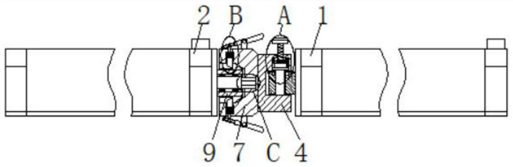
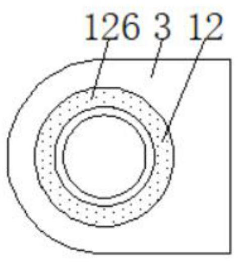
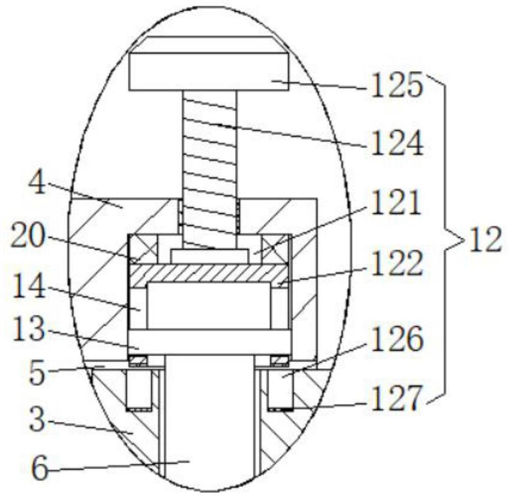
[0034] Embodiment 2: The difference from Embodiment 1 is that the inside of the fixed plate 24 is provided with an angle fixing mechanism 12, and the angle fixing mechanism 12 includes a movable groove 121, a gear sleeve 122, a screw rod 124, a rotating block 125, an annular placement groove 126 and a tooth Teeth 127, the movable groove 121 is set on the top of the fixed groove one 5 inner wall, the screw rod 124 is arranged on the top of the fixed plate one 3, the tooth sleeve 122 is movably connected inside the movable groove 121, and the bottom end of the screw rod 124 penetrates to the movable groove 121 The inside is fixedly connected to the top of the gear sleeve 122, the surface of the screw rod 124 is threadedly connected to the inside of the fixed plate 24, the rotating block 125 is fixedly connected to the top of the screw rod 124, and the annular placement groove 126 is opened on the top of the fixed plate 13. Teeth 127 are provided at the bottom of the inner wall of...

Embodiment 3

[0035] Embodiment 3: The difference from Embodiment 1 is that the top of the fixed rod 6 extends to the inside of the tooth sleeve 122 and is fixedly connected with the support plate 13. Both sides of the tooth sleeve 122 are provided with openings 14, and both sides of the support plate 13 are Pass through the opening 14 and be fixedly connected with the inner wall of the movable groove 121. By setting the support plate 13 and the opening 14, the top of the fixed rod 6 can be supported, and at the same time, the gear sleeve 122 can be limited to prevent the gear sleeve 122 from moving up and down. The phenomenon of rotation occurs when the gear sleeve 122 moves, which improves the stability of the gear sleeve 122 when it moves.

Embodiment 4

[0036] Embodiment 4: The difference from Embodiment 1 is that the limiting mechanism 15 includes a pressing plate 151, a sleeve block 152, a movable rod 153, a connecting plate 154, a limiting plate 155 and a limiting groove 156, and the pressing plate 151 is hinged to the fixed plate through a pin On the right side of the top and the bottom of the third 7, the cover block 152 is fixedly connected to the left side of the fixed plate three 7, the limit groove 156 is opened in the inside of the fixed plate three 7, and the limit groove 156 is located at the top and bottom of the fixed groove two 8, The limiting plate 155 is movably connected inside the limiting groove 156, the side of the limiting plate 155 close to the sleeve 9 penetrates to the inside of the slot 11, and the connecting plate 154 is fixedly connected to the side of the limiting plate 155 away from the sleeve 9 The side of the connecting plate 154 away from the limiting plate 155 penetrates to the outside of the ...


PUM


Abstract

The invention discloses an LED lamp that can be spliced ​​and used in multiple groups. The sides are fixedly connected with a fixed plate one, the left side of the fixed plate one is provided with a fixed plate two, the right side of the fixed plate two is provided with a fixed groove one, and the bottom of the inner wall of the fixed groove one is fixedly connected with a fixed rod . In the present invention, by holding the second body of the LED lamp and pushing it to the right, the clamping block is inserted into the slot, and at the same time, the limit mechanism fixes the second body of the LED lamp, thereby achieving high installation and disassembly efficiency and facilitating the installation and removal of multiple sets of strips. The advantages of splicing LED lights solve the problem that the existing strip LED lights are fixed by bolts and other fasteners when splicing, the installation and disassembly efficiency is low, and it is not convenient to use multiple groups of splicing. The LED lights used in multi-group splicing are highly practical, easy to operate, and convenient for people to use.

Description

technical field [0001] The invention relates to the technical field of LED lamps, in particular to an LED lamp that can be spliced ​​and used in multiple groups. Background technique [0002] LED is a solid-state semiconductor device that can convert electricity into visible light, and can directly convert electrical energy into light energy. LED lights are usually a collection of multiple LED combinations. [0003] Strip LED lamps can be used as strip light sources, and have gradually replaced the traditional lamp structure. They appear in various occasions that require lighting. In these lighting fields, not only multiple independent According to the lighting needs, multiple strip LED lights are combined and spliced, such as splicing into a straight line or splicing into a triangle, etc. However, the existing strip LED lights are fixed by bolts and other fasteners when splicing. The efficiency of installation and disassembly is low, and it is not convenient for multi-grou...

Claims


Application Information

Patent Timeline
Patent Type & Authority Patents(China)
IPC IPC(8): F21S4/24F21V21/005F21V19/02F21Y115/10
CPCF21V19/02F21V21/005F21S4/24F21Y2115/10
Inventor 曾斌
Owner 曾斌
Why Eureka
Try Eureka