Tool and method for detecting inner wall of hollow shaft/pipe by using endoscope

A hollow shaft and tube inner wall technology, applied in the field of surface defect detection of parts, can solve problems such as low efficiency, image distortion, and cumbersome operation methods, and achieve the effects of improving integrity, quick disassembly, and wide application range

Inactive Publication Date: 2019-03-19
AECC AVIATION POWER CO LTD
View PDF12 Cites 1 Cited by
  • Summary
  • Abstract
  • Description
  • Claims
  • Application Information

AI Technical Summary

Problems solved by technology

This method mainly has the following three problems in the operation process: (1) The shaking of the operator's hand and the relative rotation of the part and the probe will cause the distance between the probe and the surface to be inspected to change, which will easily cause image distortion, so it needs to be constantly adjusted. The focal length is used to achieve the best clarity of the image; (2) the probe is poorly connected to the continuous inspection site during large-area surface inspection, and the surface to be inspected is easy to be missed; (3) due to the distortion in the process of penetrating into the cavity In this case, the specific orientation of the probe in the cavity is uncertain, which makes it impossible to intuitively determine the specific position of the defect after the defect is found
[0004] The existence of the above problems makes the operation method of using an endoscope to detect the inner wall of the hollow shaft / pipe more cumbersome, inefficient, and has the possibility of missing detection, and the determination of the defect location is not intuitive

Method used


Image

  • Tool and method for detecting inner wall of hollow shaft/pipe by using endoscope
  • Tool and method for detecting inner wall of hollow shaft/pipe by using endoscope
  • Tool and method for detecting inner wall of hollow shaft/pipe by using endoscope

Examples


Embodiment Construction

[0048] The present invention will be further described in detail below in conjunction with specific embodiments, which are explanations of the present invention rather than limitations.

[0049] The purpose of the present invention is to propose a method for improving the reliability of endoscope detection of hollow shaft / pipe by improving the detection technology of endoscope and assisting the tooling used to detect the inner wall of shaft / pipe parts.

[0050] Firstly, the tooling of the present invention will be described in detail in conjunction with the accompanying drawings.

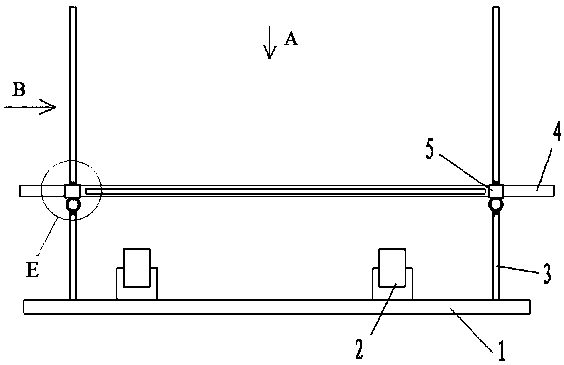
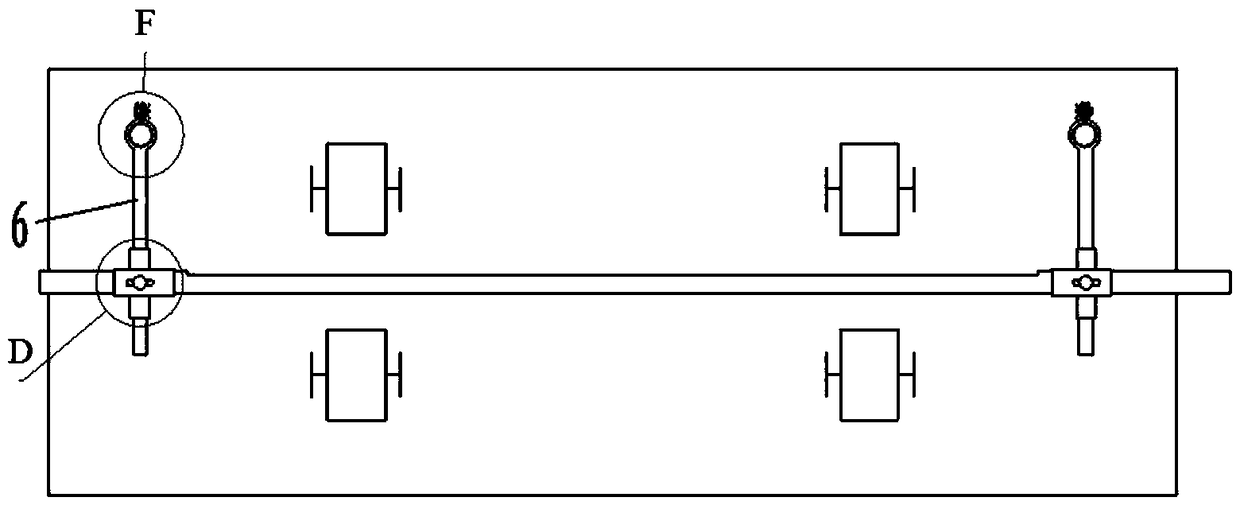
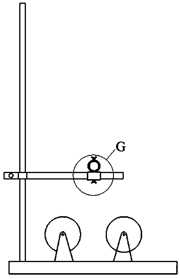
[0051] An endoscope of the present invention detects the tooling of the inner wall of the hollow shaft / pipe, and its structure is as follows figure 1 , figure 2 and image 3 as shown, figure 1 The enlarged picture is as follows Figure 5 as shown, figure 2 The enlarged picture is as follows Figure 4 and Figure 6 as shown, image 3 The enlarged picture is as follows Figure 7 As shown, i...


PUM


Abstract

The invention relates to a tool and method for detecting an inner wall of a hollow shaft/pipe by using an endoscope. The tool is successively provided with at least two roller groups along the axial direction on a same horizontal plane. The axes of rollers in the two roller groups are parallel to each other, the rollers are symmetrically arranged on the horizontal plane, the axial direction of a casing pipe is parallel to the axial direction of the roller, the casing pipe is fixed above the roller groups, and a groove which is wider than an endoscope probe is processed on the wall of the casing pipe. According to the method, the hollow shaft/pipe is supported by the rollers to rotate coaxially, and a distance between the endoscope probe and the inner wall of the hollow shaft/pipe is fixed,so that a focal distance between the probe and a detected surface does not need to be re-adjusted in the detection process. The image coverage range of the probe can be determined at a unit step length stretching into the casing pipe, so that the omission of the detection work can be avoided. Meanwhile, since the probe moves in parallel in the casing pipe, the specific orientation of the probe inthe cavity of the hollow shaft/pipe is definite. The position of a defect can be rapidly determined according to the stretching distance of the probe in the casing pipe and the direction of the casing pipe groove.

Description

technical field [0001] The invention relates to the detection of surface defects of parts, in particular to an endoscope tool for detecting the inner wall of a hollow shaft / pipe and a method thereof. Background technique [0002] With the development of aero-engine technology, the performance requirements of aero-engine parts are getting higher and higher, and the detection of the most harmful surface defects has also attracted more and more attention. As an indirect visual inspection method, endoscope inspection is widely used in surface quality inspection methods of parts. The function of the endoscope is mainly used for the detection of parts that are not accessible to the human eye, such as the detection of the inner wall of the hollow shaft / tube. [0003] At present, the probe of the endoscope is mostly connected to the observation equipment through a flexible optical cable. When in use, the probe is extended above the surface of the part to be inspected through a hand...

Claims


Application Information

Patent Timeline
Patent Type & Authority Applications(China)
IPC IPC(8): G01N21/954
CPCG01N21/954G01N2021/9548
Inventor 刘兴勇徐亚亚王婵王晓滨周文博周嘉梁唐建朝
Owner AECC AVIATION POWER CO LTD
Why Eureka
Try Eureka