Rod lens array coupled linear radiation detector with radiation coming from a side direction of scintillating material

a radiation detector and linear radiation technology, applied in the direction of x/gamma/cosmic radiation measurement, radioation controlled devices, instruments, etc., can solve the problems of high cost of fop, inconvenient use, and high x-ray path, so as to achieve constant focal length and low cost. , the effect of high volum

Inactive Publication Date: 2019-10-24
YANG LINBO
View PDF4 Cites 0 Cited by
  • Summary
  • Abstract
  • Description
  • Claims
  • Application Information

AI Technical Summary

Benefits of technology

[0029]Another advantage of the present invention is that the existing low-cost and high-volume production of the rod lens arrays allows the X-ray detector machines according to the present invention to also be produced at low cost and high volume.
[0030]Another advantage of the present invention is that focal length is constant in the air and one dimensional focusing procedure is simple.
[0031]Another advantage of the present invention is that it makes it possible to manufacture a small, portable X-ray detector machine.
[0032]Another advantage of the present invention is that most of time this invention is for high energy X-ray application, in this case a thicker scintillating materials layer is needed. It is easier to make fixture to hold scintillating material layer without considering optical plate.
[0033]Yet another advantage of the present invention is that with the small enclosure size required and the methods of radiation shielding, it is possible to design dual or multi X-ray scanning machines enclosed in the same space currently used to enclose a single X-ray scanning machine. The dual or multi X-ray scanning machines can be used for scanning a target simultaneously in different X-ray energy ranges for better detection.
[0034]Still another advantage arising from the small size and shielding properties of the present invention is that it is possible to implement a three-dimensional X-ray scanner, in which two scanning detectors system are positioned orthogonally with respect to each other.

Problems solved by technology

Direct coupling is by far the most efficient way, but it also makes LDA on-axis of X-ray path and therefore the most susceptible to radiation damages.
FOP is usually very expensive, large scale use of FOP at high energy X-ray application might not be cost effective.
However, problems arise in the prior arts.
The first disadvantage of prior arts is substantial light loss.
But it is well known fact that using FOP would result in much smaller signal than that at Direct Coupling.
The second disadvantage of prior arts is that, qualitatively, if an optical transmission plate is placed between rodlens and focal spot, the overall optical system focal length would be changed just like that in a single lens system.
The third disadvantage of prior arts is that, quantitatively, the change of system focal length would not only depend on the geometrical size of the optical transmission plate or optical transmission pin but also depends on the nature of optical plate or pin material its self because different optical material would have different index of refraction.
The fourth disadvantage of prior arts is that it would introduce a complicated two dimensional focusing process.
In practice, trying to perform 2D both X and Y direction focusing is time-consuming.
The fifth disadvantage of the prior arts is that, usually a high quality piece of long single piece narrow plate, mirror or prism is required in order to meet the performance requirements.
This kind of high precision long, narrow mirror or prism is not only very expensive, but also there is a limit of max length that a manufacturer can produce.
The sixth disadvantage of the prior arts is that, if there are no long pieces of mirror or prism available, then cascade of multiple shorter pieces would be necessary.
As a result, gaps between each plate, mirror or prism are inevitable.
The sizes of the gaps are usually very difficult to control.
The seventh disadvantage of the prior arts is that a plate, a mirror or a prism is usually in a radiation path, and this kind of optical components tends to turn brown or yellow after receiving certain amount of X-ray doses so that light transmission efficiency will be seriously affected.
When the browning becomes so severe it would make the whole optical system unusable.
The eighth disadvantage of the prior arts is that, practically, only rodlens with relatively longer focal length can be used.
As a result, prior arts can only choose to use rodlens with relatively longer focal length that will make system less sensitive.
The ninth disadvantage of the prior arts is that, in practice, longer piece of glass tend to be brittle and easy to break so that whole system becomes unusable.
If an X-ray detector system is equipped with this kind of optical components, a small accidental drop of package during the shipping will cause damage of optical components.
As a result, its reliability is very low.
The tenth disadvantage of the prior arts is that, in practice, long narrow optical components are very difficult to handle.
It also has safety hazard.
It is always possible for glass of sharp edges cause injury of finger cut.
In view of many disadvantages, so far commercial viability of prior arts has been minimal.

Method used


Image

  • Rod lens array coupled linear radiation detector with radiation coming from a side direction of scintillating material
  • Rod lens array coupled linear radiation detector with radiation coming from a side direction of scintillating material
  • Rod lens array coupled linear radiation detector with radiation coming from a side direction of scintillating material

Examples


Embodiment Construction

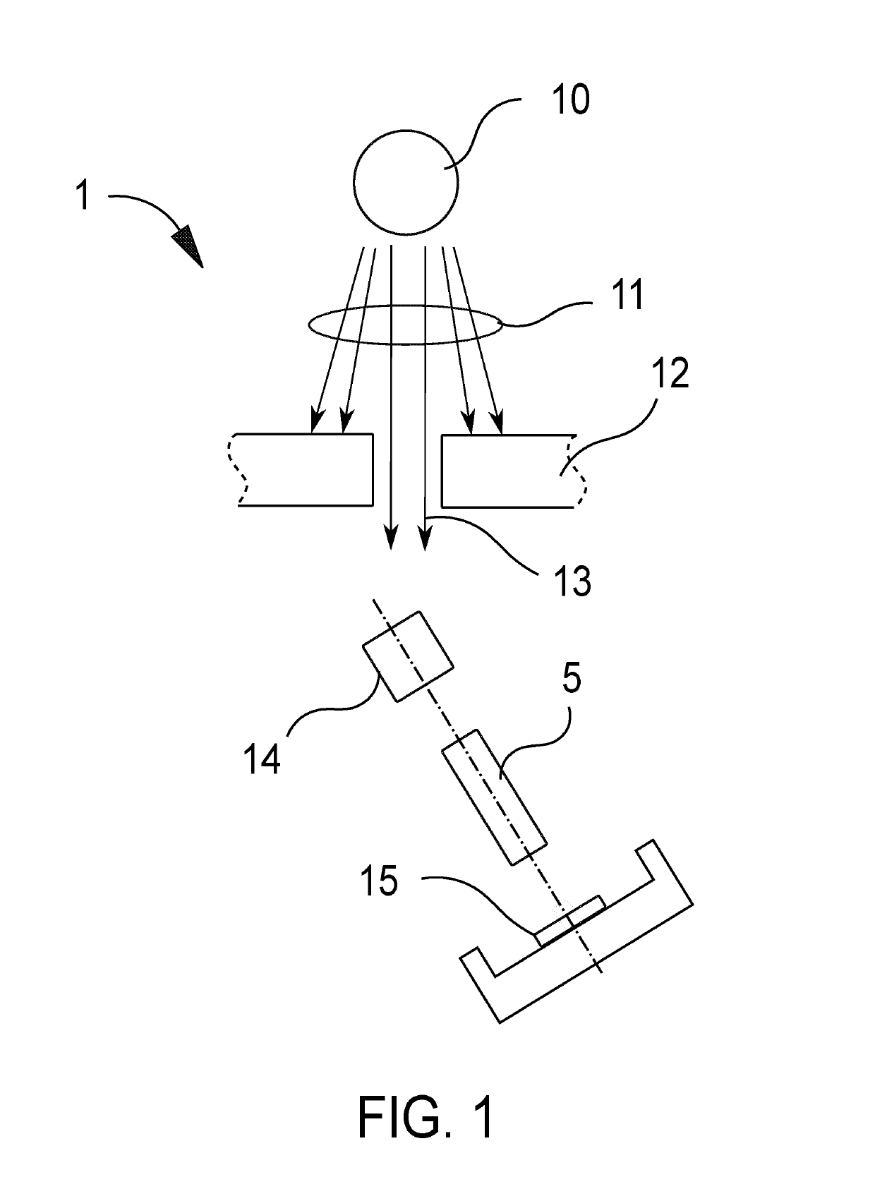
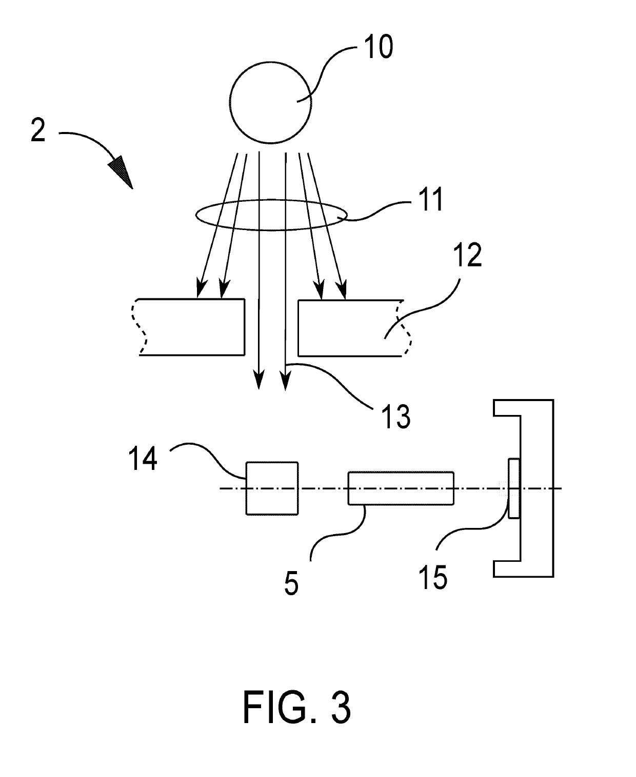
[0047]The present invention is a linear X-ray detector system 1.

[0048]The detector system 1 is based on a unique focusing principle that utilizes a rod lens array 5.

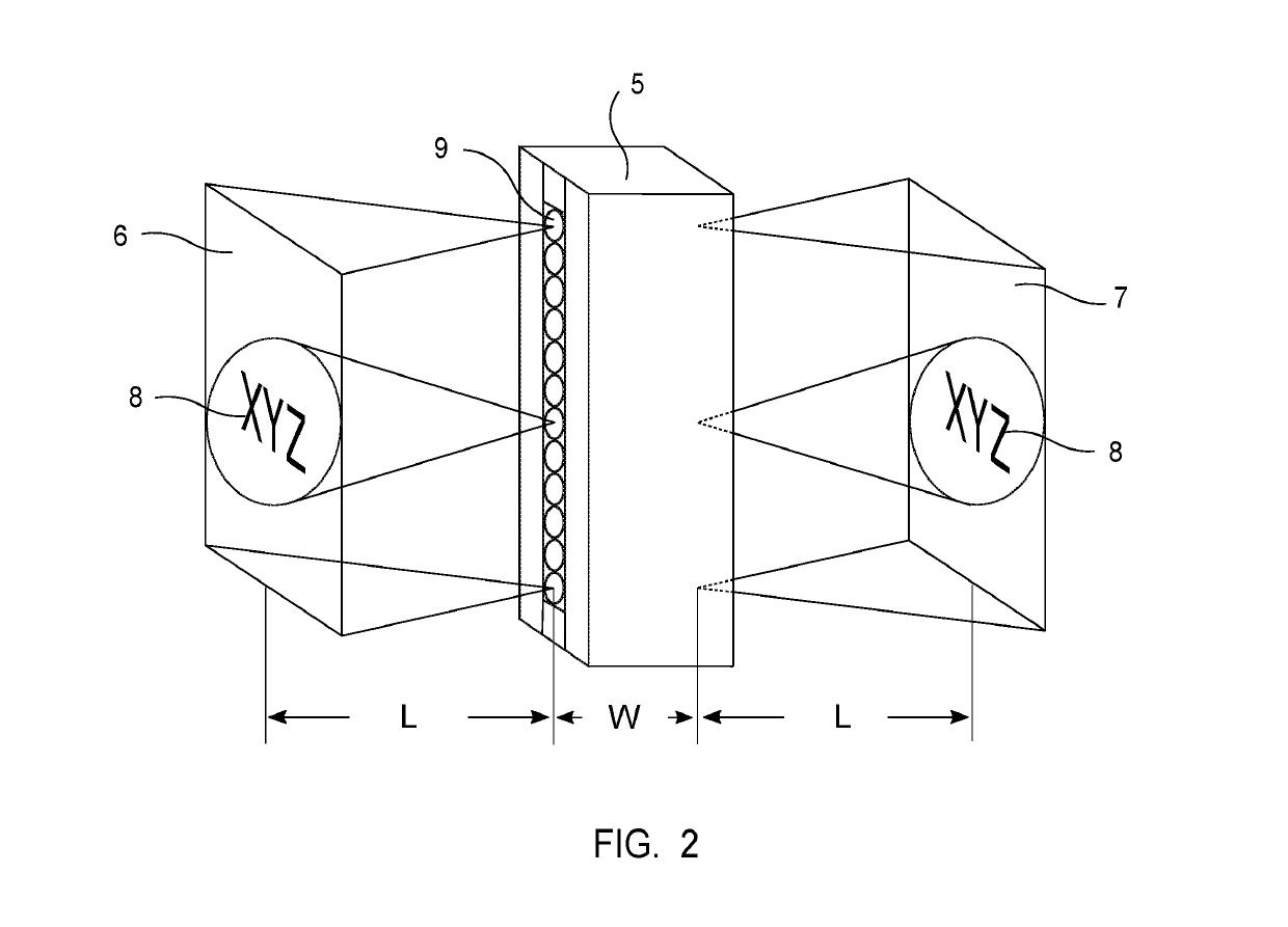
[0049]A typical rod lens array 5 is illustrated in FIG. 2. Selections of rod lens include commercially available single row and dual row rod lens.

[0050]The X-ray detector system 1 comprises scintillating material 14, a rod lens array 5 and image sensor array 15. In light pass, there is no other unnecessary optical media like optical glue, glass, plastics, plate, prism, mirror etc in order to preserve light transmission with high efficiency.

[0051]Some of the viable options for the scintillating material are Gd2O2S:Tb (GOS or GADOX), CsI(TI), CdWO4, or GAGG:Ce etc.

[0052]Scintillating material 14 is placed in an object image plane 6 and is used to convert the impinging X-ray energies into visible light which can be detected by the image sensor array 15 in image plane 7.

[0053]There is also shielding material 12 and slit aper...


PUM


Abstract

A linear radiation detector array system that is based on a unique focusing principle reduces or eliminates the X-ray radiation damage on the electrical components of the detector system. The system includes a layer of scintillating material, a rod lens array, and an array of image sensors. The layer of scintillating material, such as Gd2O2S:Tb (GOS or GADOX), CsI(TI), CdWO4, or GAGG:Ce is placed on an image plane and is used to convert the impinging radiation energies into visible light which can be detected efficiently by the image sensor array. The rod lens array is used to transmit and focus the visible light after the radiation flux has been converted. The photon energy of the visible light is collected with a scanning image sensor array.

Description

BACKGROUND OF THE INVENTIONField of the Invention[0001]The present invention pertains generally to the field of radiation solid-state imagers and displays, and more particularly is an improved method that structurally alters the optical path to reduce or avoid radiation damage to the semiconductor components while maintaining overall relative high sensitivity.BACKGROUND OF THE INVENTION[0002]Image sensor arrays of indirect conversion are usually only sensitive to light with wavelengths at or near the visible spectrum.[0003]Therefore, the arrays require an X-ray-to-visible-light converter in order to detect the X-rays or other radiation. To this end, X-ray sensitive scintillating materials, such as the Gd2O2S:Tb (GOS or GADOX), CsI(TI), CdWO4 or GAGG:Ce have been used.[0004]These materials greatly enhance the detection efficiency of higher energy X-rays in the image sensor arrays through the ability of the scintillating materials to scintillate and emit visible light photons proporti...

Claims


Application Information

Patent Timeline
Patent Type & Authority Applications(United States)
IPC IPC(8): G01T1/20H01L27/146
CPCG01T1/2002H01L27/14629H01L27/14663G01T1/2018G01T1/202G01T1/20185
Inventor YANG, LINBO
Owner YANG LINBO
Why Eureka
Try Eureka