Undercarriage damping structure for near space solar energy unmanned aerial vehicle

A technology for solar-powered drones and adjacent space, which is applied in the field of landing gear shock-absorbing structures, which can solve the problems of high spring fatigue strength, reduced service life, and increased use costs, and achieve the effect of enhancing the buffering effect and ensuring the service life

Active Publication Date: 2019-03-22
浙江翔龙航空科技有限公司
View PDF6 Cites 12 Cited by
  • Summary
  • Abstract
  • Description
  • Claims
  • Application Information

AI Technical Summary

Problems solved by technology

[0004] The purpose of the present invention is to solve the shortcomings in the prior art, such as: most of the traditional landing gears use springs for landing buffering and shock absorption, the effect of buffering and shock absorption is limited, and the fatigue strength of a single spring buffer is too large for the spring itself , will reduc...

Method used


Image

  • Undercarriage damping structure for near space solar energy unmanned aerial vehicle
  • Undercarriage damping structure for near space solar energy unmanned aerial vehicle
  • Undercarriage damping structure for near space solar energy unmanned aerial vehicle

Examples


Embodiment Construction

[0025] The following will clearly and completely describe the technical solutions in the embodiments of the present invention with reference to the accompanying drawings in the embodiments of the present invention. Obviously, the described embodiments are only some, not all, embodiments of the present invention.

[0026] In describing the present invention, it should be understood that the terms "upper", "lower", "front", "rear", "left", "right", "top", "bottom", "inner", " The orientation or positional relationship indicated by "outside", etc. is based on the orientation or positional relationship shown in the drawings, and is only for the convenience of describing the present invention and simplifying the description, rather than indicating or implying that the referred device or element must have a specific orientation, so as to Specific orientation configurations and operations, therefore, are not to be construed as limitations on the invention.

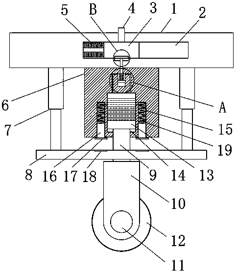
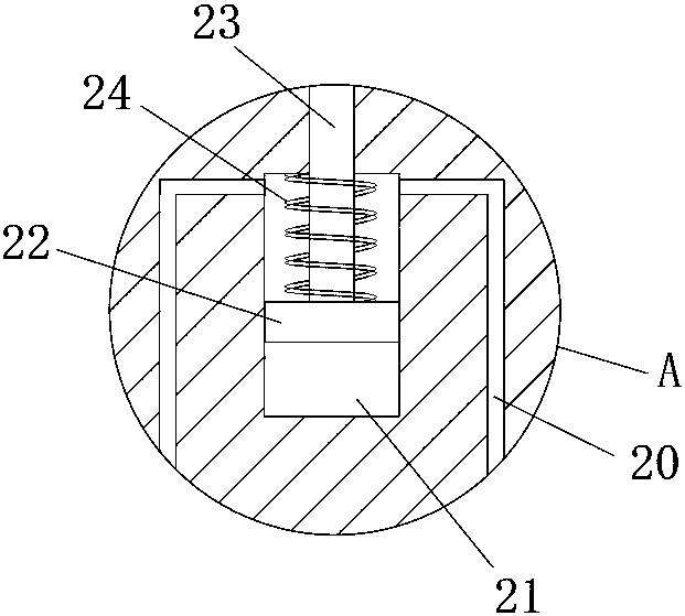
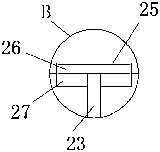
[0027] refer to Figure ...


PUM


Abstract

The invention discloses an undercarriage damping structure for a near space solar energy unmanned aerial vehicle. The undercarriage damping structure comprises a mounting plate, wherein a chute is formed in the mounting plate; a weighing sliding block is connected inside the chute in a sliding manner; an adjusting pin is fixedly connected with one side of the weighing sliding block; an elastic mechanism is arranged inside the chute; a fixing plate is connected with the mounting plate through two groups of first buffer mechanisms; a sealing base is fixedly connected with the bottom side of themounting plate; a piston rod is fixedly connected with the fixing plate; a walking device is arranged at one end of the piston rod; and a first sealing cavity is formed inside the sealing base. By reducing the distance between a first strong magnet and a second strong magnet, the repulsive force between the first strong magnet and the second strong magnet can be gradually increased, two-stage buffer damping is resulted by the repulsive force of the first strong magnet and the second strong magnet, and then due to cooperation with a buffer spring for damping, the fatigue intensity of the bufferspring can be shared while a buffer effect is improved.

Description

technical field [0001] The invention relates to the technical field of landing gear of unmanned aerial vehicles, in particular to a landing gear shock-absorbing structure for near-space solar-powered unmanned aerial vehicles. Background technique [0002] Near space refers to the airspace 20 to 100 kilometers away from the ground. Due to its important development and application value, it has attracted widespread attention in the world. UAV is also an important survey tool in airspace. UAV + industry application is the real The current application in aerial photography, agriculture, plant protection, infectious disease monitoring, surveying and mapping, news reporting, power inspection, disaster relief, etc. has greatly expanded the use of drones themselves, and developed countries are also actively expanding industry applications and the development of drone technology. [0003] Landing gear is used for the take-off and landing of drones, especially for landing, the cushio...

Claims


Application Information

Patent Timeline
IPC IPC(8): B64C25/62
CPCB64C25/62B64U2101/00
Inventor 朱光玺
Owner 浙江翔龙航空科技有限公司
Why Eureka
Try Eureka