Wet clutch friction plate

A wet clutch and friction plate technology, applied in the clutch field, can solve the problems of separation lag, increased oil viscosity, unsmooth driving control of motorcycles, etc., and achieve the effect of solving incomplete separation and simple structure and production.

Inactive Publication Date: 2008-08-13
刘珍利
View PDF0 Cites 8 Cited by
  • Summary
  • Abstract
  • Description
  • Claims
  • Application Information

AI Technical Summary

Problems solved by technology

However, since the wet clutch is immersed in the engine oil environment, when the clutch is separated, since the active friction plate and the driven friction plate are in the form of surface separation, the engine oil attached to the surface of the active friction plate and the driven friction plate will form adhesion when the clutch is tightly attached, resulting in ...

Method used


Image

  • Wet clutch friction plate
  • Wet clutch friction plate

Examples


Embodiment Construction

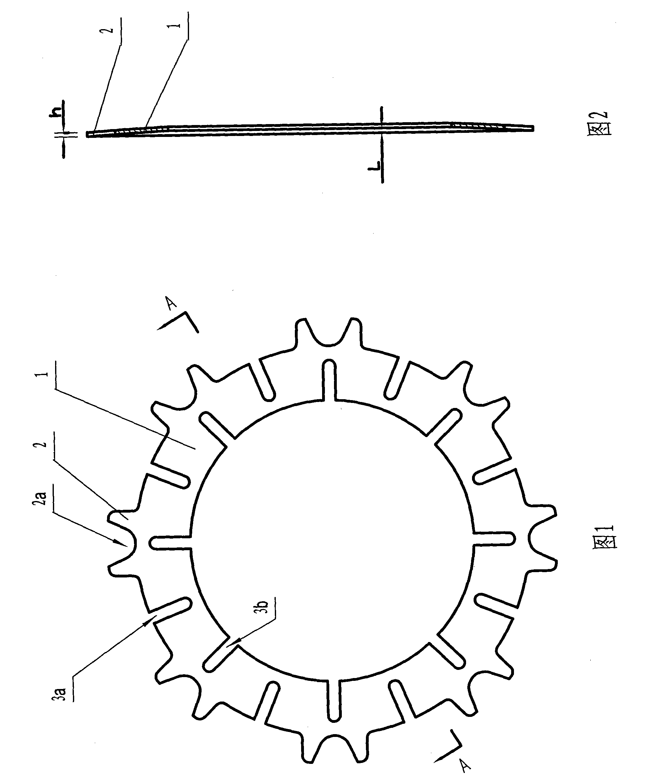
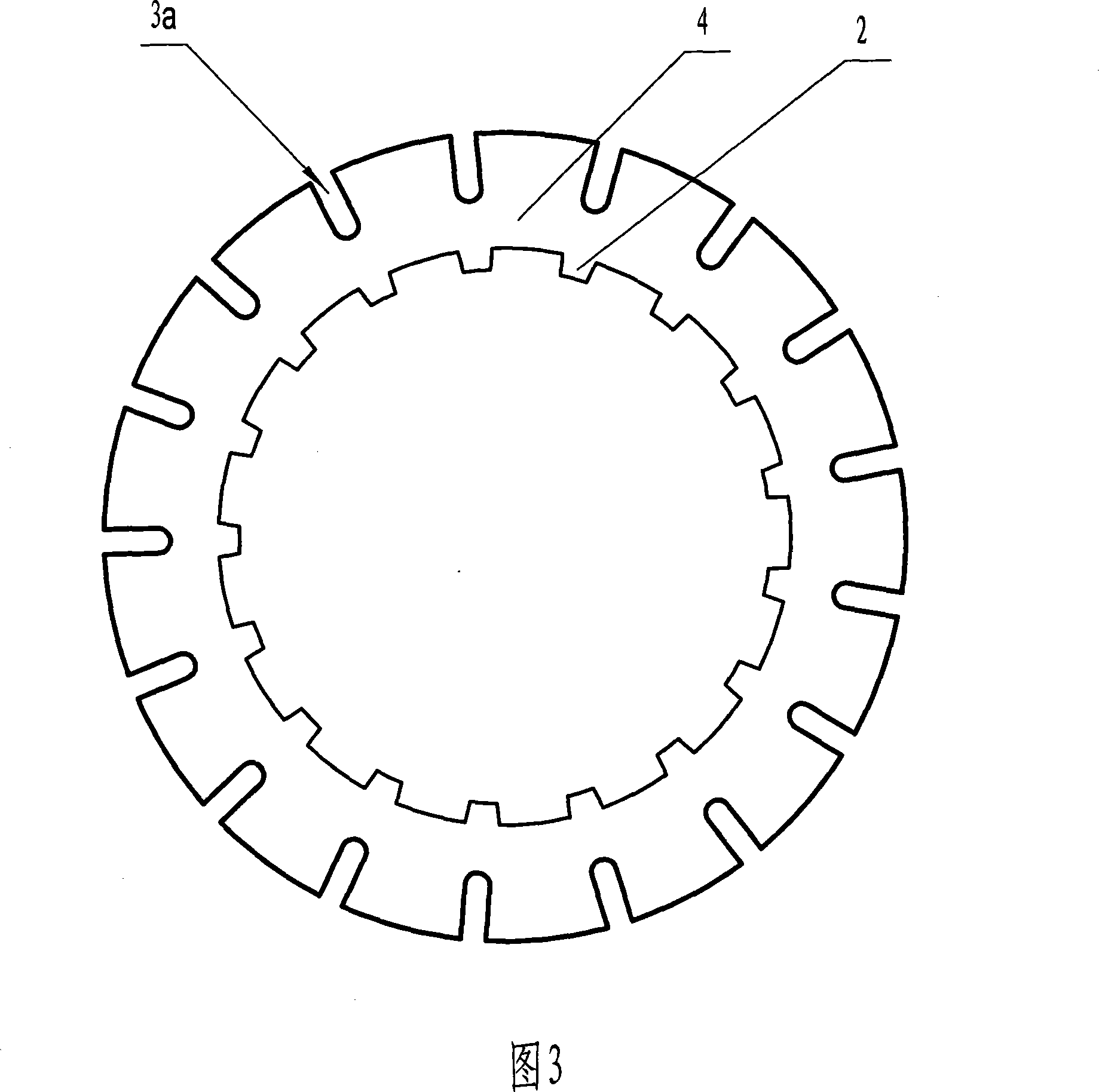
[0013] Referring to Fig. 1 and Fig. 2, it is an embodiment of the friction plate of the present invention used in the active friction plate of the wet clutch of the motorcycle engine. The active friction plate 1 is a ring-shaped steel sheet formed by punching a thin steel plate, and there are a plurality of outer convex teeth 1a integrally formed with the active friction plate 1 for circumferential fixing uniformly distributed on its outer circumference. The active friction plate 1 has 8 outer protruding teeth 1a for circumferential fixing, which are used to engage with the grooves on the clutch cover. Each outer tooth 1a is provided with a notch 2 for the release spring. A plurality of radially extending opening grooves 3b are evenly distributed on the inner circumference of the active friction plate 1, and between two adjacent outer convex teeth 1a for circumferential fixing on the outer circumference of the active friction plate 1 can also be Radial open grooves 3 a are pr...


PUM

PropertyMeasurementUnit
Thicknessaaaaaaaaaa

Abstract

The present invention discloses a wet clutch friction wafer which is annular sheet steel, many circumferential fixed protruding gears are placed inner circumference or outer circumference equably, and the friction wafer is annular sheet steel with axial elastic deformation, the end of it is curved surface. When clutch is separated, it can assure full separation between friction wafers by self axial elastic deformation eliminating moebius oil conglutination between friction wafers.

Description

technical field [0001] The invention relates to the field of clutches, in particular to a friction plate of a wet clutch. Background technique [0002] At present, the clutches used in motorcycle engines are mostly wet clutches. This kind of wet clutch works in an environment immersed in engine oil, and can rely on engine oil to reduce wear and take away heat. This kind of wet clutch is generally equipped with multiple sets of friction plates, and the torque is transmitted through the contact between the active friction plates of multiple sets of friction plates and the axial end faces of the driven friction plates to form power transmission; through the active friction plates of multiple sets of friction plates and the driven friction plates Disengagement of the plates interrupts torque transmission to cut off power transmission. However, the existing friction plates all adopt rigid friction plates whose axial end faces are straight pulls. When the clutch is engaged, the a...

Claims


Application Information

Patent Timeline
IPC IPC(8): F16D13/64
Inventor 刘珍利
Owner 刘珍利
Why Eureka
Try Eureka