Rotary electronic gear shifting device

An electronic shifter and rotary technology, which is applied to components with teeth, belts/chains/gears, mechanical equipment, etc., can solve the problems of poor user operation, no buffering effect, short service life, etc. Save labor, reduce production cost and use cost, and have long service life

Pending Publication Date: 2019-03-22
金华斯迈尔电子科技有限公司
View PDF0 Cites 5 Cited by
  • Summary
  • Abstract
  • Description
  • Claims
  • Application Information

AI Technical Summary

Problems solved by technology

[0002] The traditional motor vehicle shift mechanism usually uses a bullet with a spring for shift positioning. The above structure has the following disadvantages: 1. The noise generated when shifting is relatively large; 2. It will cause wea

Method used


Image

  • Rotary electronic gear shifting device
  • Rotary electronic gear shifting device
  • Rotary electronic gear shifting device

Examples


Embodiment 1

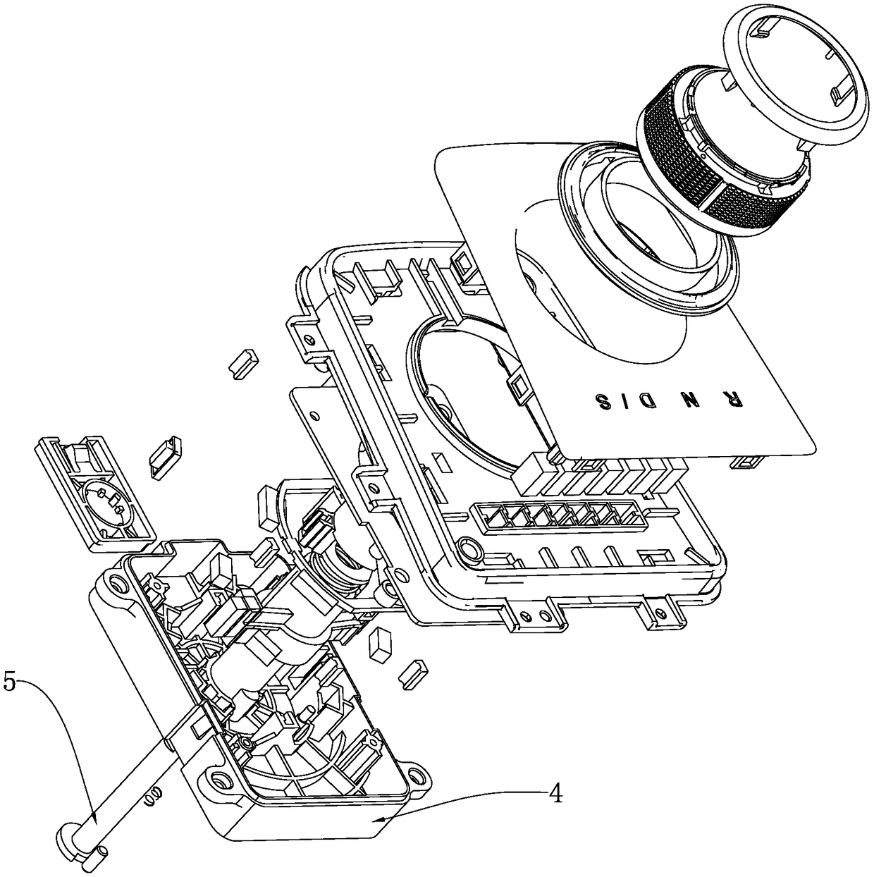
[0042] Such as Figure 1-7 As shown, a rotary electronic shifter includes a housing 4 that can be mated with a motor vehicle, a knob mechanism, and a rotating shaft 5 that is connected to the knob mechanism after passing through the housing 4 . The knob mechanism includes a first magnetic assembly installed in the housing 4 , a third magnetic assembly arranged around the rotating shaft 5 , a second magnetic assembly located between the first magnetic assembly and the third magnetic assembly, and a stopper.

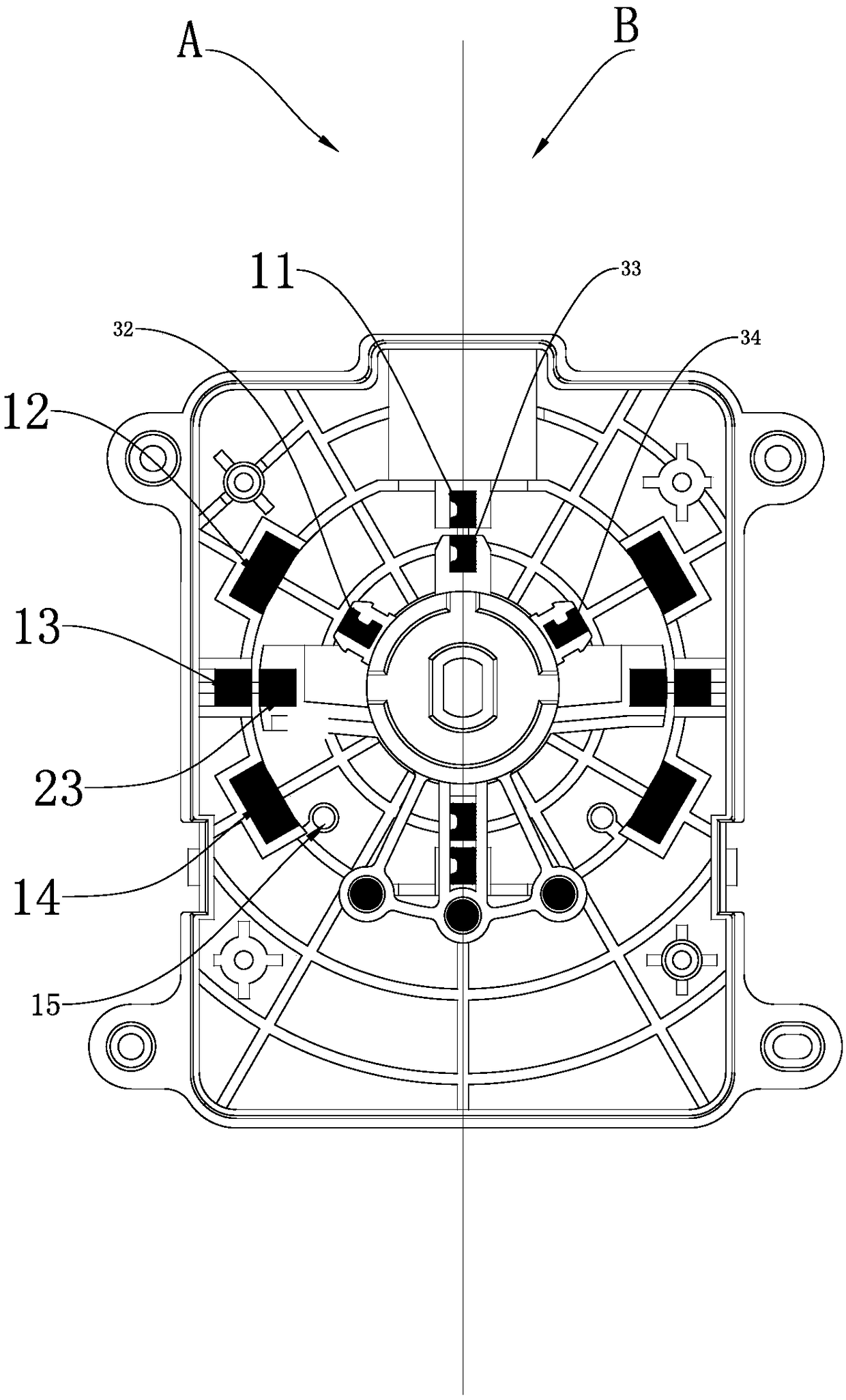
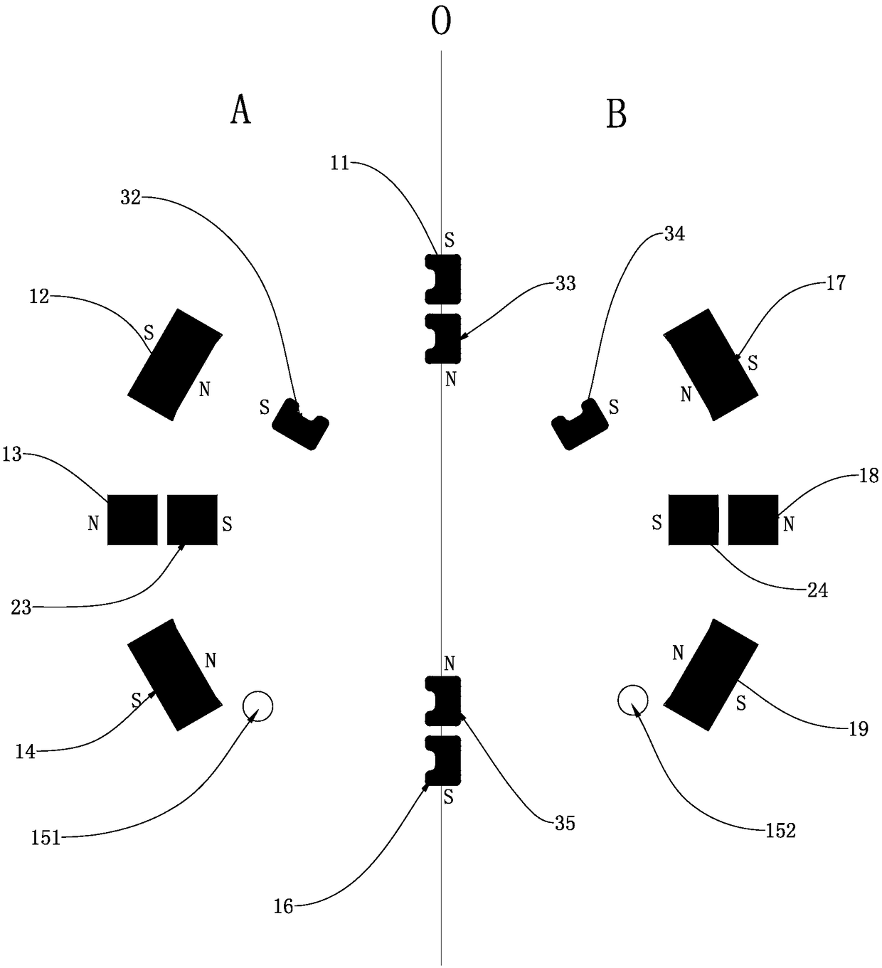
[0043] Specifically, a circle radiating outward with the rotation axis 5 as the center in the housing 4 is provided with a symmetrical first area A and a second area B. The first area A and the second area B take O as the axis of symmetry, and the first area A is equipped with a first magnetic assembly, a second magnetic assembly, a third magnetic assembly and a stopper; the first magnetic assembly includes a limiting magnetic body 11, another limiting magnetic body 16, and ...

Embodiment 2

[0057] Such as Figure 17-24As shown, the difference between the present embodiment and the first embodiment is that four symmetrical areas are set in the casing 4 with the rotation axis 5 as the center to radiate outward, namely area C, area D, area E and area F. , area C and area D, area E and area F take O1 as the axis of symmetry, area E and area C, area D and area F take O2 as the axis of symmetry, and area C is equipped with a first magnetic assembly, a second magnetic assembly, A third magnetic assembly and a stopper.

[0058] The first magnetic assembly includes a limit magnet 61, a magnet 1 62 and a magnet 2 63 arranged at intervals, and the magnet 1 62 is buckled in the groove 621 of the housing 4, wherein the groove 621 faces the rotating shaft 5 with a The opening exposes the magnetic pole of the first magnet 62 outside the slot body 621, and the second magnet 63 is buckled in the slot body 631 of the housing 4, wherein the slot body 631 has an opening on the side...


PUM


Abstract

The invention discloses a rotary electronic gear shifting device. The rotary electronic gear shifting device comprises a shell, a rotary knob mechanism and a rotating shaft, wherein the rotary knob mechanism comprises a first magnetic assembly, a third magnetic assembly, a second magnetic assembly and a blocking part; when the rotary knob mechanism is in an initial state, the first magnetic assembly sucks and fixes the second magnetic assembly and the third magnetic assembly, external force F1 is applied, the rotary knob mechanism is circumferentially rotated, the third magnetic assembly is separated from the first magnetic assembly and rotates along with the rotating shaft, and when rotating to touch the second magnetic assembly, the third magnetic assembly automatically resets; and whenexternal force F2 larger than F1 is applied, the rotary knob mechanism is circumferentially rotated, the third magnetic assembly can drive the second magnetic assembly to circumferentially rotate to the blocking part, and the third magnetic assembly and the second magnetic assembly automatically reset. According to the rotary electronic gear shifting device, the structure is simple, friction noiseis not generated, the hand feeling is good, utilization experience of users is good, the service life is long, and operation is effort-saving.

Description

technical field [0001] The invention belongs to the technical field of motor vehicle gear shifting, in particular to a rotary electronic gear shifter. Background technique [0002] The traditional motor vehicle shift mechanism usually uses a bullet with a spring for shift positioning. The above structure has the following disadvantages: 1. The noise generated when shifting is relatively large; 2. It will cause wear and tear during contact and the service life is short; There is a sudden change in force, there is no cushioning effect, and impact will occur; 4. After a long period of use, due to the attenuation of the force, the user's operation feels poor. Contents of the invention [0003] In order to overcome the deficiencies of the prior art, the present invention provides a rotary electronic shifter with long service life, no noise during operation, and good operating feel. [0004] The technical solution adopted by the present invention to solve the technical problem ...

Claims


Application Information

Patent Timeline
IPC IPC(8): F16H59/02F16H61/24
CPCF16H59/0278F16H61/24
Inventor 董小雷陶吉黄鹏邬晨欢徐鑫薛渝胜程良洪
Owner 金华斯迈尔电子科技有限公司
Why Eureka
Try Eureka