High-pressure multi-stage pressure reducing valve

A pressure reducing valve, high pressure technology, applied in the direction of valve lift, valve details, valve device, etc., can solve the problems of unresolved valve sealing problems, inconsistent fluid speed, easy vibration, etc., to reduce equipment maintenance costs and avoid fluid speed Inconsistent, avoiding clogged or stuck effects

Pending Publication Date: 2019-03-22
华润电力(贺州)有限公司
View PDF2 Cites 4 Cited by
  • Summary
  • Abstract
  • Description
  • Claims
  • Application Information

AI Technical Summary

Problems solved by technology

Its shortcoming is that it only solves the problem of valve pressure reduction, but does not solve the problem of valve sealing
Its disadvantages are: the valve core adopts a cantilever structure with one section of guidance and one section of free and unconstrained, and the unconstrained end of the valve core is impacted by high-pressure fluid, which makes the valve core eccentric and causes inconsistent gaps, which is easy to generate vibration and not only produces noise. Also, because of the change in the size of the gap, the fluid velocity is inconsistent, forming erosion, and quickly damaging the valve core

Method used


Image

  • High-pressure multi-stage pressure reducing valve
  • High-pressure multi-stage pressure reducing valve

Examples


Embodiment 1

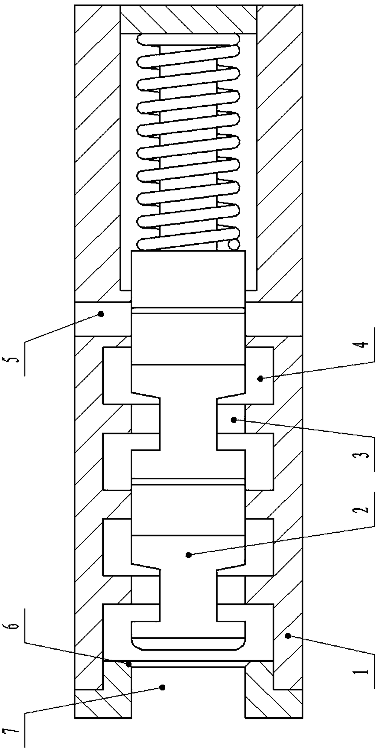
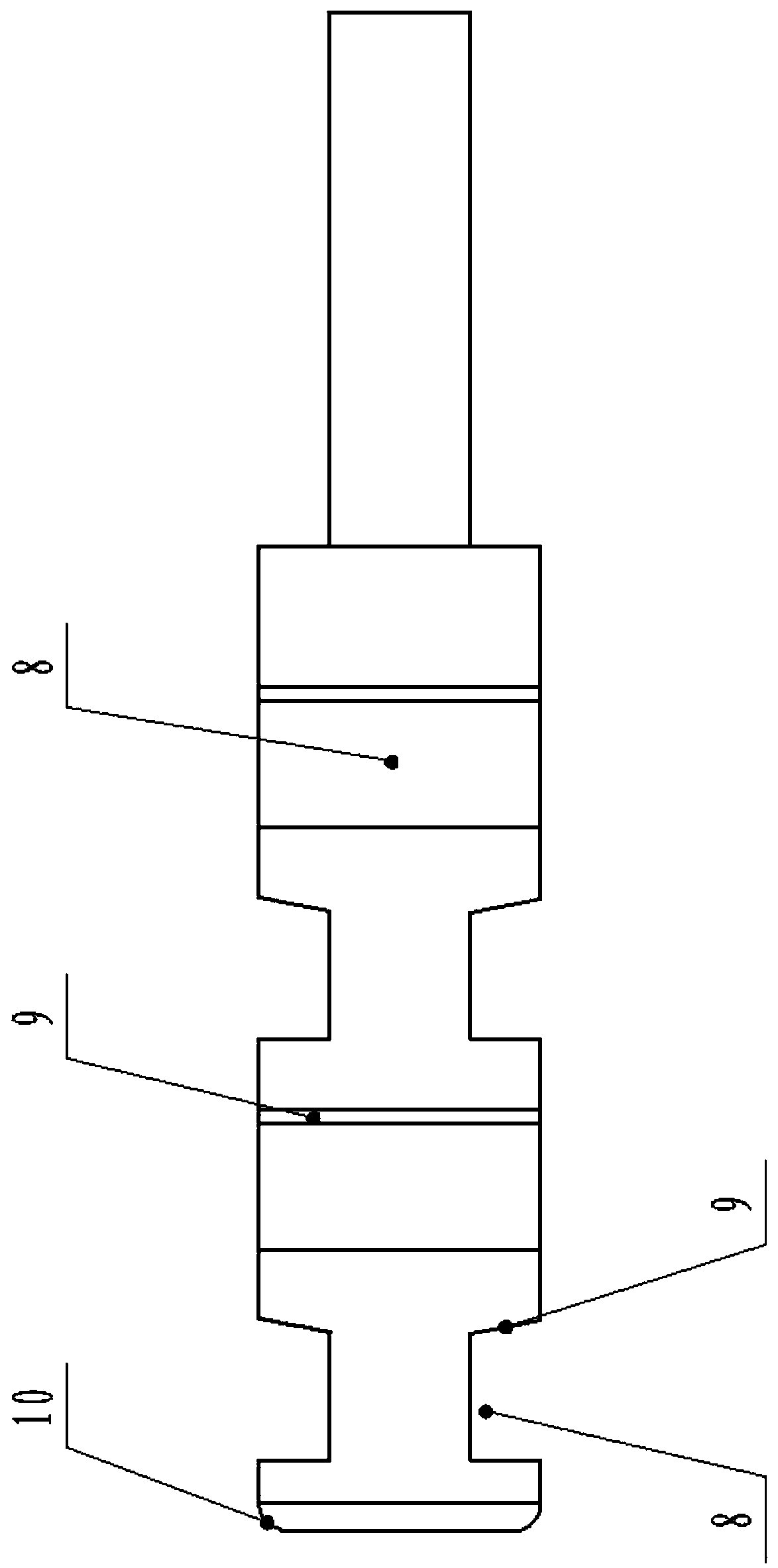
[0031] Such as figure 1 As shown, the present invention includes a housing 1, the housing 1 is provided with a fluid inlet 7 and a fluid outlet 5, and three sealing bosses 3 are arranged on the inside, and two grooves 4 are formed between the sealing bosses 3; The pressure reducing valve also includes a spool 2 connected to the sealing boss 3, the spool 2 is provided with two diversion grooves 8, and an angle α is set between the axially adjacent diversion grooves 8, and the value of α is 10 °.

[0032] In this embodiment, when the present invention is started, the high-pressure fluid enters the housing 1 from the fluid inlet 7, and enters the space formed by the groove 4 and the diversion groove 8 along the space formed by the valve core 2 and the edge of the sealing boss 3, and the depressurization The low-pressure fluid (relative to the pressure of the fluid inlet 7) finally flows out from the fluid outlet 5 to complete the function of decompression. Since this embodiment ...

Embodiment 2

[0034] The difference from Embodiment 1 is that four sealing bosses 3 are arranged on the inner side of the housing 1, three grooves 4 are formed between the sealing bosses 3, and three diversion grooves 8 are arranged on the valve core 2, Two diversion grooves 8 form a group, arranged radially symmetrically, and an angle α is set between axially adjacent diversion grooves 8, and the value of α is 30°.

[0035] Compared with Embodiment 1, this embodiment adds a sealing surface, which improves the sealing performance of this embodiment, and the angle between the axially adjacent diversion grooves 8 is increased, and the valve core 2 and the housing 1 are enlarged. The contact area effectively increases the guidance of the valve core 2, reduces the vibration between the valve core 2 and the housing 1, and reduces the noise of this embodiment.

Embodiment 3

[0037]The difference from Embodiment 2 is that: five sealing bosses 3 are arranged on the inner side of the housing 1, four grooves 4 are formed between the sealing bosses 3, and four diversion grooves 8 are arranged on the valve core 2, An angle α is set between axially adjacent diversion grooves 8 , and the value of α is 45°; the surface of the diversion grooves 8 away from the fluid inlet 7 is provided with a diversion slope 9 .

[0038] Compared with embodiment 2, this embodiment adds a sealing surface, which further improves the sealing performance of this embodiment, and the angle between the axially adjacent diversion grooves 8 increases, further increasing the distance between the valve core 2 and the shell. The contact area of ​​the body 1 further increases the guidance of the valve core 2, further reduces the vibration between the valve core 2 and the housing 1, and further reduces the noise of this embodiment.


PUM


Abstract

The invention discloses a high-pressure multi-stage pressure reducing valve. The high-pressure multi-stage pressure reducing valve comprises a shell, wherein a fluid inlet and a fluid outlet are arranged on the shell; a plurality of sealing bosses are arranged on the inner side of the shell; a groove is formed between every two sealing bosses; the multi-stage pressure reducing valve further comprises a valve core connected to the sealing bosses; a plurality of guiding grooves are formed in the valve core; the number of the guiding grooves is equal to the number of the grooves; the axially adjacent guiding grooves are arranged with an angle alpha, and of the angle alpha is greater than 0 DEG and less than or equal to 90 DEG; the guiding grooves are radially and symmetrically arranged with every two guiding grooves falling into one group; a flow guiding bevel is arranged on the surface, away from the fluid inlet, of each guiding groove; chamfers are arranged on the inner side of the sealing boss at the fluid inlet of the shell; and a rounding is arranged on the end, near to the fluid inlet, of the valve core. When the high-pressure multi-stage pressure reducing valve is connected tothe fluid, the distance between the chamfers and the rounding is larger than the distance between the flow guiding bevels to the sealing boss closest to the flow guiding bevels. The high-pressure multi-stage pressure reducing valve is suitable for high pressure fluid, and is also suitable for low pressure fluid.

Description

technical field [0001] The invention relates to the field of valves, in particular to a high-pressure multi-stage decompression valve. Background technique [0002] High pressure valve refers to a valve working at a nominal pressure PN of 10-80Mpa. It is a control component in a fluid delivery system and has functions such as cut-off, regulation, flow diversion, prevention of backflow, pressure stabilization, flow diversion, or overflow relief. Widely used in various industries. Due to the widespread use of high-pressure technology, the performance of ultra-high-pressure valves in ultra-high-pressure systems directly affects the reliability, safety, efficiency and service life of the entire system. It is particularly important in systems that require frequent pressure boosting and pressure relief. We all know that the main failure causes of ultra-high pressure valves are: cavitation and erosion wear, and there are many factors that affect cavitation and erosion, mainly incl...

Claims


Application Information

Patent Timeline
Patent Type & Authority Applications(China)
IPC IPC(8): F16K1/00F16K1/36F16K47/02F16K47/04F16K47/08F16K27/02
CPCF16K1/00F16K1/36F16K27/02F16K47/02F16K47/04F16K47/08
Inventor 韩超郑运郭升晓林建华许明阳窦长江赵天锦陈泽前王旭文
Owner 华润电力(贺州)有限公司
Why Eureka
Try Eureka