Double-sided coating mechanism
A double-sided coating and coating technology, which is applied to the device and coating of the surface coating liquid, can solve the problems of low production efficiency, hang-up, high loss of equipment and materials, and prevent residual glue from sticking material, simple structure, anti-slip effect
- Summary
- Abstract
- Description
- Claims
- Application Information
AI Technical Summary
Problems solved by technology
Method used
Image
Examples
Embodiment 1
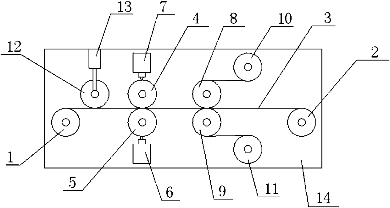
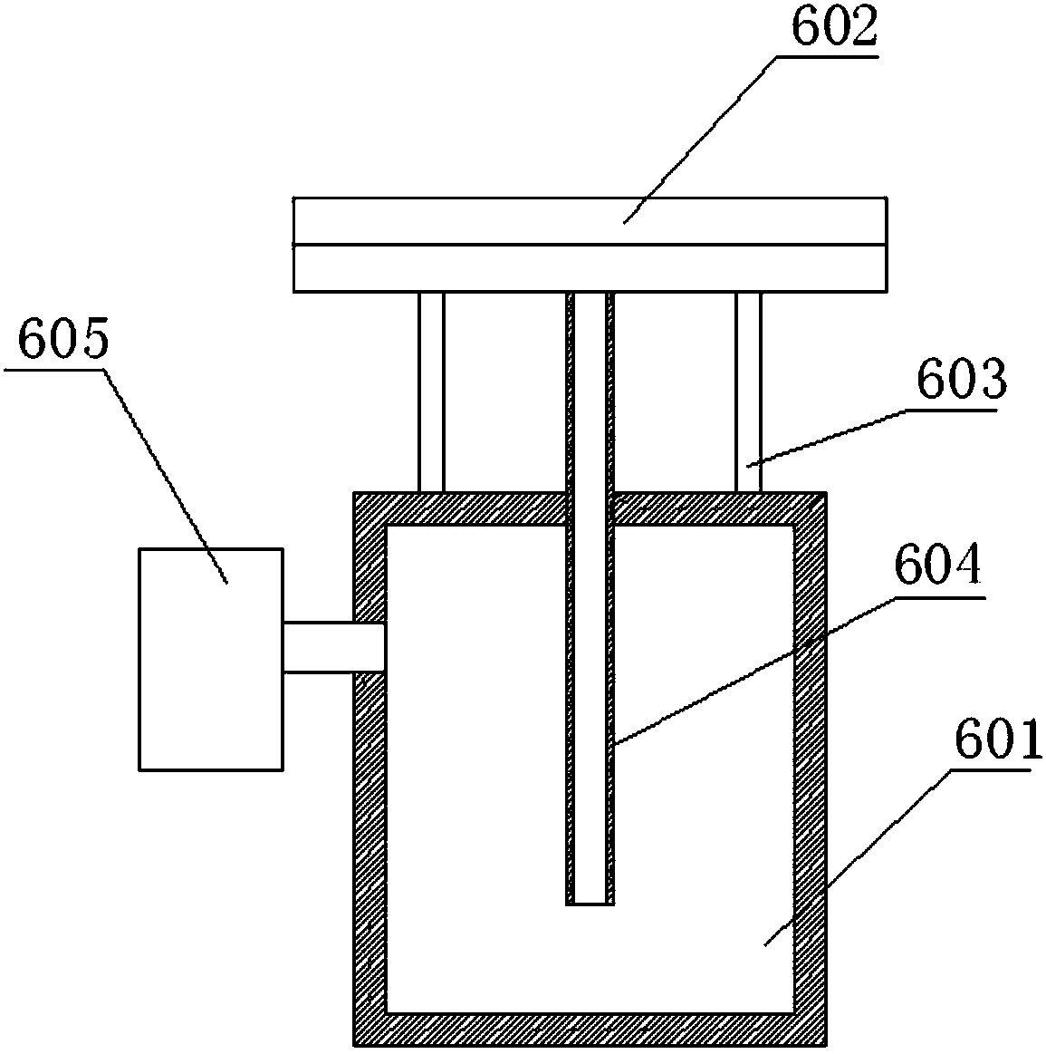
[0023] Such as figure 1 A double-sided coating mechanism shown includes a frame 14, a feed roller 1 and a take-up roller 2 fixed on the frame 14, and the feed roller 1 and the take-up roller 2 are arranged horizontally. An upper coating roller 4 and a lower coating roller 5 are arranged between the described upper material roller 1 and the receiving roller 2, and the roller surface of the upper coating roller 4 and the lower coating roller 5 is provided for passing through the coating material. The gap between the material, the upper pressure roller 8 and the lower pressure roller 9 are also arranged between the lower coating roller 5 and the receiving roller 2, and there is a gap between the upper pressure roller 8 and the lower pressure roller 9, and the One side of the upper coating roller 4 is provided with an upper coating device 7, and the coating die on the coating device 7 is in contact with the roller surface of the upper coating roller 4, and one side of the lower co...
Embodiment 2
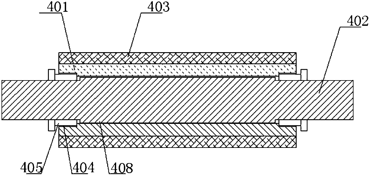
[0028] Such as image 3 and 4 The shown upper coating roller 4 and the lower coating roller 5 are the same coating roller, comprising a roller body 401, a central axis 402 arranged at the center of the roller body 401, and the outer surface of the roller body 401 is covered with a layer Release layer 403, the roll body 401 includes a round roll 101, grooves 102 evenly arranged on the circumferential surface of the round roll 101 and parallel to the center line of the round roll 101; the release layer 403 includes a base layer 301 and a release tape 302 fixedly pasted on the base layer 301, the base layer 301 is in close contact with the groove 102 of the round roller 101.
[0029] The roller body 401 is fixedly connected to the central shaft 402, and the material of the roller body 401 currently used is an aluminum roller body, which is relatively light and can consume less energy. The anti-sticking layer provided The 403 fixed difference is wound on the roller body 401, which...
Embodiment 3
[0032] On the basis of Example 1, such as image 3 , Figure 5 As shown, the center hole 406 of the roller body 401 is provided with a chute 407 parallel to the center line of the center hole 406, and the axial direction of the central shaft 402 is provided with a chute 407 that matches the chute 407. Block 408 , the sliding block 408 is inserted into the slide groove 407 to connect the roller body 401 with the central shaft 402 . The fixing method between the roller body 401 and the central shaft 402 is fixed by the slider 408 and the chute 407, which effectively prevents the relative movement between the central shaft 402 and the roller body 401, resulting in the central shaft 402 not being able to The roller body 401 is driven to roll, and the roller body 401 and the central shaft 402 adopt a split type instead of an integrated type, which can facilitate the replacement of the roller body during use and is more convenient to use. At the same time, in order to enable the c...
PUM
 Abstract
Description
Claims
Application Information
 - R&D
- Intellectual Property
- Life Sciences
- Materials
- Tech Scout
- Unparalleled Data Quality
- Higher Quality Content
- 60% Fewer Hallucinations
Browse by: Latest US Patents, China's latest patents, Technical Efficacy Thesaurus, Application Domain, Technology Topic, Popular Technical Reports.
© 2025 PatSnap. All rights reserved.Legal|Privacy policy|Modern Slavery Act Transparency Statement|Sitemap|About US| Contact US: help@patsnap.com


