Industrial equipment punching machine with fixing function

An industrial equipment, fixed function technology, applied in metal processing equipment, large fixed members, drilling/drilling equipment, etc., can solve the problems of inability to clamp the plate, unstable fixation, and inability to adjust the punching position, etc. The effect of efficiency

Active Publication Date: 2019-03-26
温岭市山市金德利电器配件有限公司
View PDF16 Cites 6 Cited by
  • Summary
  • Abstract
  • Description
  • Claims
  • Application Information

AI Technical Summary

Problems solved by technology

The industrial equipment punching machine with fixed function, through the setting of the fixing device, the motor drives the rotating rod to rotate, so that the rotating block pulls the push-pull rod, so that the extrusion block pushes the first fixed block to fix the industrial equipment, which solves the problem of The situation that the industrial equipment is not fixed firmly when punching holes avoids the situation where the position of the punching hole occurs due to the loose fixing of the industrial equipment. Through the setting of two punching devices and two fixing devices, the punching The machine can continuously punch holes for industrial equipment; the disadvantage of this invention is that it cannot be clamped for plates of different thicknesses, and the punching position cannot be adjusted according to different needs.

Method used


Image

  • Industrial equipment punching machine with fixing function
  • Industrial equipment punching machine with fixing function
  • Industrial equipment punching machine with fixing function

Examples


specific Embodiment approach 1

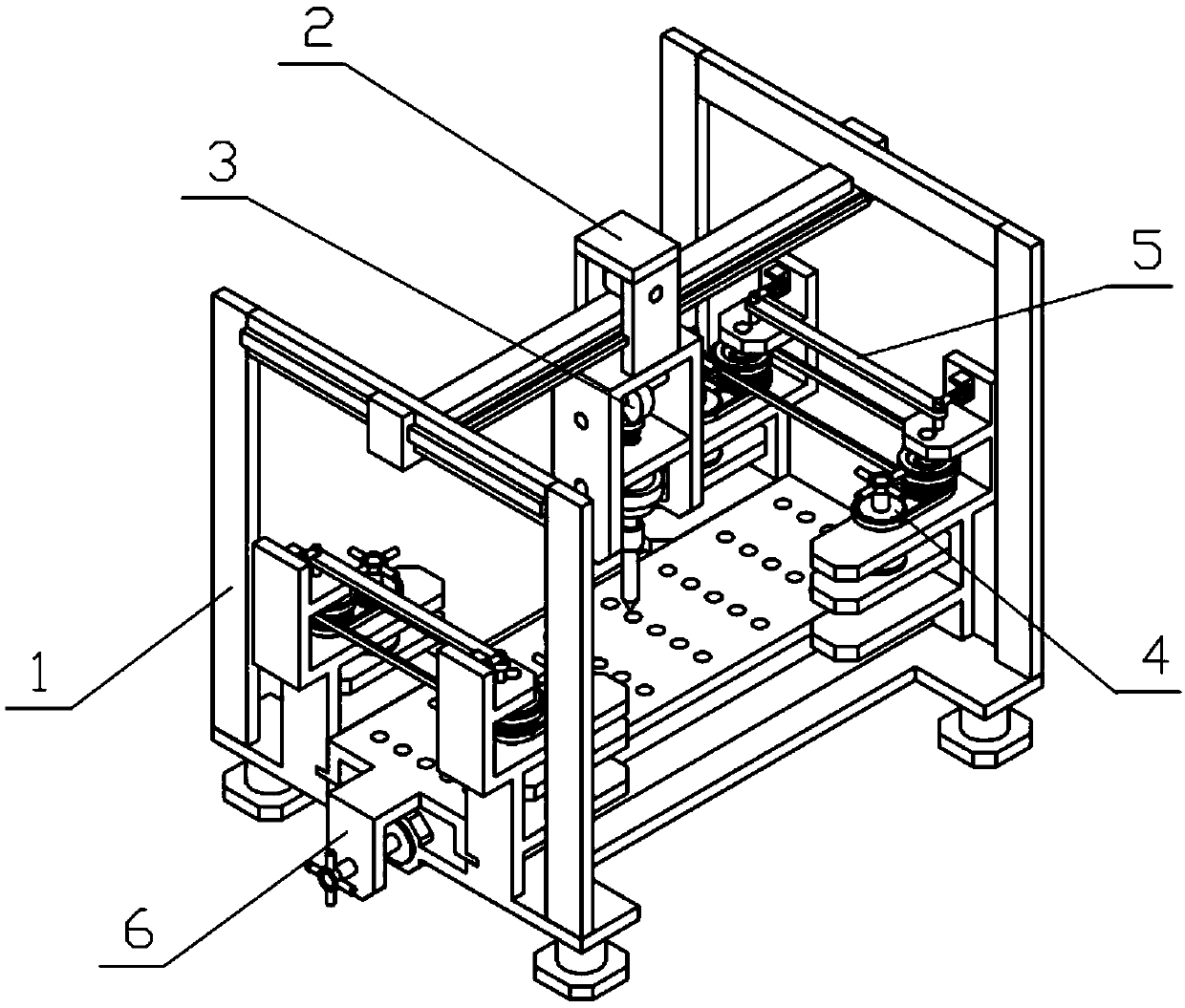
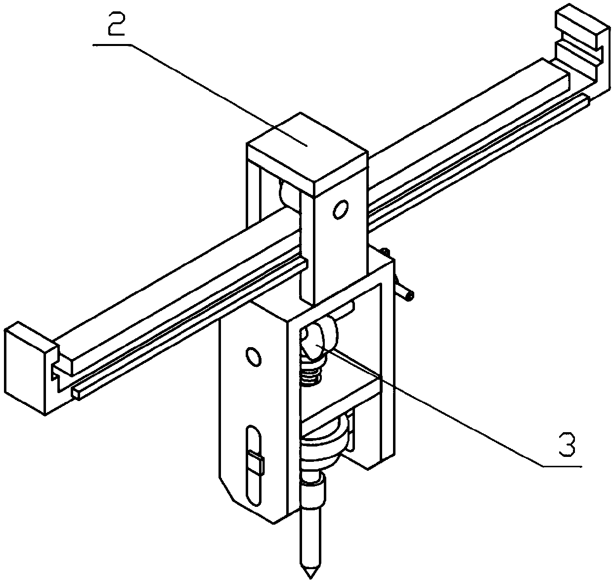
[0033] Combine below Figure 1-10 Describe this embodiment, an industrial equipment punching machine with a fixed function, including an integral bracket 1, an adjustment bracket 2, a punching mechanism 3 and a clamping mechanism 4, which can clamp plates of different thicknesses through the clamping mechanism 4, And the four clamping mechanisms 4 can independently clamp and carry out linkage clamping through the linkage mechanism 5. When the four clamping mechanisms 4 are independently clamped, plates with different thicknesses and shapes can be used, and the four clamping mechanisms 4 can be used through the linkage mechanism. 5. The efficiency of clamping can be increased when performing linkage clamping. By adjusting the bracket 2, the relative position of the punching mechanism 3 can be adjusted, so that the punching position of the punching mechanism 3 can be adapted to different use needs. The punching mechanism 3 can The boards with different thicknesses are punched, a...

specific Embodiment approach 2

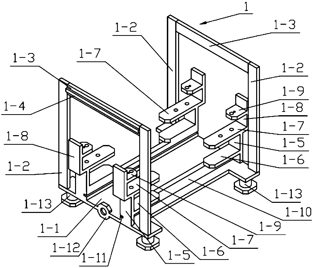
[0038] Combine below Figure 1-10 Describe this embodiment, this embodiment will further explain the first embodiment, the integral bracket 1 also includes linkage support plate I1-8, linkage support plate II1-9, sliding plate 1-10, sliding groove 1-11, push bottom plate 1-12 and support feet 1-13, the four clamping top plates 1-7 are fixedly connected with linkage support plates I1-8, and the four linkage support plates I1-8 are all fixedly connected with linkage support plates II1-9, Two sliding plates 1-10 are fixedly connected between the four supporting plates II 1-5, and sliding grooves 1-11 are arranged on the two sliding plates 1-10, and the pushing base plate 1-12 is fixedly connected to the supporting base plate 1-1 On one side of the support base plate 1-1, the four corners of the lower end of the support base plate 1-1 are fixedly connected with support feet 1-13.

specific Embodiment approach 3

[0039] Combine below Figure 1-10 This embodiment will be described. This embodiment will further describe the second embodiment. The punching mechanism 3 further includes a push handle I3-10, which is fixedly connected to one end of the push shaft 3-8.


PUM


Abstract

The invention relates to punching mechanisms, in particular to an industrial equipment punching machine with the fixing function. The industrial equipment punching machine comprises an integral support, an adjusting support, a punching mechanism, four clamping mechanisms, a linkage mechanism and a supporting mechanism. The clamping mechanisms can be used for clamping different thicknesses of plates. The four clamping mechanisms can independently conduct clamping and conducts linkage clamping through the linkage mechanism. The four clamping mechanisms can be used for clamping the plates with different thicknesses when conducting independent clamping. The four clamping mechanisms can improve the clamping efficiency when conducting linkage clamping through the linkage mechanism. The relativeposition of the punching mechanism can be adjusted through the adjusting support so that the punching position of the punching mechanism can adapt to different using requirements. The industrial equipment punching machine can punch holes in the plates with the different thicknesses through the punching mechanism, can support the plates to be punched through the supporting mechanism to protect theplates against deformation and influence on the precision due to high pressure generated in the punching process.

Description

technical field [0001] The invention relates to a punching mechanism, more specifically an industrial equipment punching machine with fixed functions. Background technique [0002] For example, the publication number CN106738042A is an industrial equipment punching machine with a fixed function, including a base, one end of the base is fixedly connected with a support frame, one side of the support frame is fixedly connected with a support plate, and the bottom of the support plate is fixedly connected with an electric telescopic rod. A punching device is fixedly connected to the bottom of the electric telescopic rod, and a fixing device is fixedly connected to the top of the base. The fixing device includes a first support block, and the first support block is fixedly connected to the top of the base. The industrial equipment punching machine with fixed function, through the setting of the fixing device, the motor drives the rotating rod to rotate, so that the rotating bloc...

Claims


Application Information

Patent Timeline
Patent Type & Authority Applications(China)
IPC IPC(8): B23B39/04B23B39/06B23Q3/06B23Q1/62B23Q1/01
CPCB23B39/04B23B39/06B23B2270/08B23Q1/012B23Q1/015B23Q1/621B23Q3/066B23Q2240/002
Inventor 张会有
Owner 温岭市山市金德利电器配件有限公司
Why Eureka
Try Eureka