An automatic steel turning device

An automatic turning and steel turning technology, which is applied in the direction of conveyor control devices, transportation and packaging, and conveyor objects, can solve the problems of not being able to fully guarantee the 90-degree turning of the steel billet, increasing the amount of manual labor, and increasing labor costs. There are no safety hazards, the effect of reducing the amount of manual labor and improving the surface quality

Active Publication Date: 2020-10-09
湖州盛特隆金属制品有限公司
View PDF9 Cites 0 Cited by
  • Summary
  • Abstract
  • Description
  • Claims
  • Application Information

AI Technical Summary

Problems solved by technology

[0002] The existing steel turning device has only 6 claws, and the steel billet can only be turned over by the hook claws, which can only be used to reject the steel billet. It cannot completely guarantee the billet to turn over at a 90-degree angle, and it is necessary to arrange full-time personnel to stand on the edge of the hydraulic valve table to operate. Increase the amount of manual labor, increase labor costs, reduce work efficiency, and have certain safety hazards
Therefore, the existing billet turning device has the problems of not being able to fully guarantee the turning of the billet at a 90-degree angle, high labor costs, reduced work efficiency, and potential safety hazards

Method used


Image

  • An automatic steel turning device
  • An automatic steel turning device

Examples


Embodiment Construction

[0016] The present invention will be further described below in conjunction with the examples, but not as a basis for limiting the present invention.

[0017] Example.

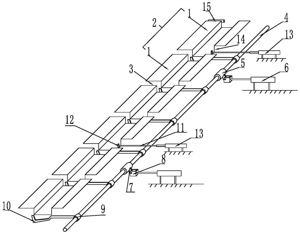
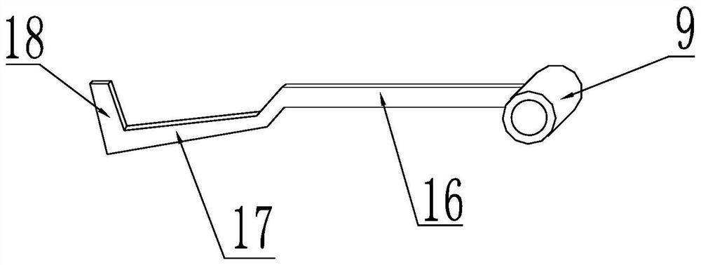
[0018] Such as figure 1 As shown, an automatic steel turning device includes a tapping roller table 2 composed of several rails 1 arranged head to tail, a steel turning gap 3 is left between adjacent rails 1, and one side of the tapping roller table 2 is provided with a The steel roller table 2 is parallel to the turning steel main shaft 4, the turning steel main shaft 4 is connected with the turning steel oil cylinder 6 through the first coupling 5, the first coupling 5 is provided with a connection block 7, and the piston of the turning steel oil cylinder 6 The rod is provided with a connecting seat 8, and the connecting block 7 is hinged with the connecting seat 8; the turning steel hook claw 10 is also connected with the turning steel hook claw 10 through the second coupling 9 on the turning steel main sh...


PUM


Abstract

The invention discloses an automatic lifting finger which comprises a steel tapping rail (2) formed through end-to-end arrangement of a plurality of rails (1), wherein a steel tapping gap (3) is reserved between every two adjacent rails (1); a steel overturning spindle (4) parallel with the steel tapping rail (2) is arranged on one side of the steel tapping rail (2); a steel overturning oil cylinder (6) is connected onto the steel overturning spindle (4) through a first coupling (5); a connecting block (7) is arranged on the first coupling (5); a connecting seat (8) is arranged on the piston rod of the steel overturning oil cylinder (6) and is hinged to the connecting block (7); a steel overturning claw (10) is connected onto the steel overturning spindle (4) through a second coupling (9);and the steel overturning claw (10) is positioned at the steel tapping gap (3). The automatic lifting finger has the characteristics of ensuring that a steel billet is overturned by 90 degrees, reducing the labor cost, improving the working efficiency and being free of a potential safety hazard.

Description

technical field [0001] The invention relates to a billet turning device, in particular to an automatic steel turning device. Background technique [0002] The existing steel turning device has only 6 claws, and the steel billet can only be turned over by the hook claws, which can only be used to reject the steel billet. It cannot completely guarantee the billet to turn over at a 90-degree angle, and it is necessary to arrange full-time personnel to stand on the edge of the hydraulic valve table to operate. The amount of manual labor is increased, the labor cost is increased, the work efficiency is reduced, and there are certain potential safety hazards. Therefore, the existing billet turning device has the problems of not being able to fully guarantee the turning over of the billet at a 90-degree angle, high labor costs, reduced work efficiency, and potential safety hazards. Contents of the invention [0003] The object of the present invention is to provide an automatic ...

Claims


Application Information

Patent Timeline
Patent Type & Authority Patents(China)
IPC IPC(8): B65G43/08B65G47/248
CPCB65G43/08B65G47/248B65G2203/042
Inventor 周海平王安新吴永康
Owner 湖州盛特隆金属制品有限公司
Why Eureka
Try Eureka