Shaft wall supporting structure

A technology of supporting structure and shaft wall, which is used in shaft equipment, shaft lining, mining equipment, etc. to ensure stability, prevent excessive deformation, and prevent damage.

Inactive Publication Date: 2019-03-26
NORTHEASTERN UNIV
View PDF11 Cites 9 Cited by
  • Summary
  • Abstract
  • Description
  • Claims
  • Application Information

AI Technical Summary

Problems solved by technology

[0006] Aiming at the problems existing in the prior art, the present invention provides a shaft wall support structure, which has the characteristics of simple structure, fast installation, and convenient construction, and can effectively deal wit...

Method used


Image

  • Shaft wall supporting structure
  • Shaft wall supporting structure
  • Shaft wall supporting structure

Examples


Embodiment Construction

[0023] The present invention will be further described in detail below in conjunction with the accompanying drawings and specific embodiments.

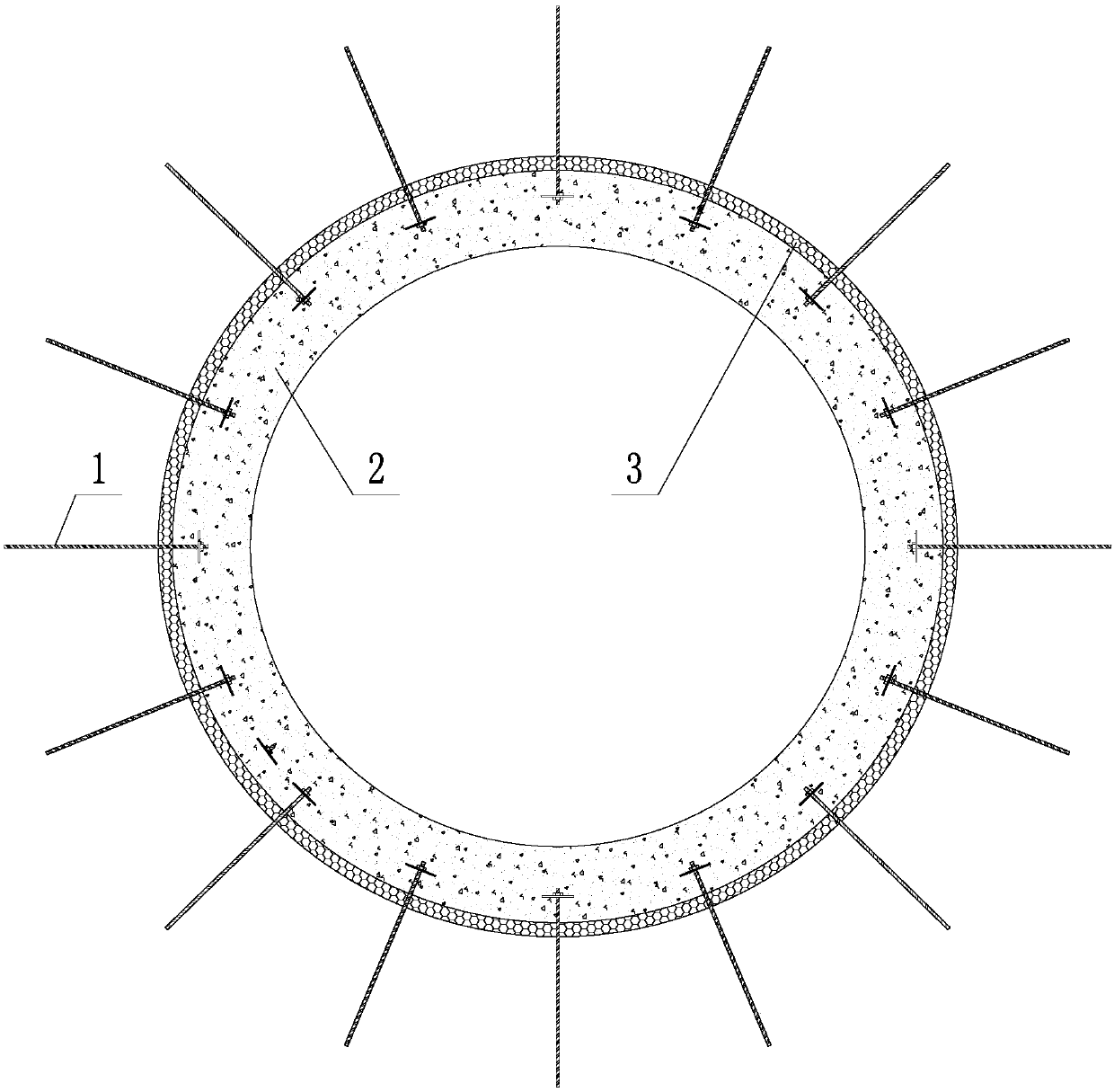
[0024] Such as figure 1 As shown, a shaft wall support structure includes an anchor rod 1 and a concrete layer 2. One end of the rod body of the anchor rod 1 is anchored in the surrounding rock of the wellbore, and the other end of the rod body of the anchor rod 1 retains a tray and a nut, and a tray and a nut are installed. The end of the rod body of the anchor rod 1 of the nut is embedded in the concrete layer 2, and the concrete layer 2 and the wellbore surrounding rock are anchored into a whole through the anchor rod 1. According to actual construction needs, the damping material layer 3 can be selected or not provided between the concrete layer 2 and the surrounding rock of the wellbore, and the anchor 1 can be an energy-releasing anchor or a non-energy-releasing anchor.

[0025] Taking the setting of the damping material layer ...


PUM


Abstract

A shaft wall supporting structure is divided into an embedded type, a welded type and an assembled type. The embedded type includes an anchor rod and a concrete layer. One end of the anchor rod is anchored in a shaft surrounding rock, a tray and a nut are retained at the other end of the anchor rod and embedded in a concrete layer, and the concrete layer and the shaft surrounding rock are anchoredinto a whole by the anchor rod; the welded type differs from the embedded type in that a steel rib framework composed of vertical ribs, horizontal ribs and pull ribs is disposed in the concrete layer, and the anchor rod does not retain a tray and a nut and is directly welded to the steel rib framework. The assembled type includes an anchor rod, a concrete layer and a cement layer. The cement layer is located between the concrete layer and the shaft surrounding rock, an outer layer steel plate is disposed between the cement layer and the concrete layer, one end of the anchor rod is anchored inthe shaft surrounding rock, the other end of the anchor rod is fixedly connected with the outer layer steel plate through a tray and a nut; and the concrete layer, the cement layer and the shaft surrounding rock are fixed to be a whole by the anchor rod. For the three types, it can be chosen according to actual requirements whether to set a damping material layer or not, and the anchor rod is anenergy release type or energy non-release type anchor rod.

Description

technical field [0001] The invention belongs to the technical field of shaft engineering support, in particular to a shaft wall support structure. Background technique [0002] At present, in the shaft wall support construction, the surrounding rock of the wellbore usually encounters the situation of large deformation of shallow soft rock, large ductile deformation of deep high-stress surrounding rock, or dynamic disasters such as rockburst in deep surrounding rock. In view of the above three situations encountered in the surrounding rock of the wellbore, the main countermeasures are secondary support technology and pressure relief blasting technology. [0003] From the perspective of principle, the secondary support technology is more suitable for the large deformation of shallow soft rock and the large ductile deformation of high-stress surrounding rock in deep. In an unstable state, when the local stress is released to a certain extent, the deformation rate of the surrou...

Claims


Application Information

Patent Timeline
IPC IPC(8): E21D5/04E21D20/00
CPCE21D5/04E21D20/00
Inventor 赵兴东李洋洋杨晓明张姝婧
Owner NORTHEASTERN UNIV
Why Eureka
Try Eureka