Optical divider

A technology of optical splitters and optical splitters, applied in light guides, optics, instruments, etc., can solve the problems of troublesome maintenance, short service life, and easy failure of optical splitters, and reduce the frequency of replacement and use costs. Low cost and long service life

Inactive Publication Date: 2019-03-26
尹红娟
View PDF1 Cites 0 Cited by
  • Summary
  • Abstract
  • Description
  • Claims
  • Application Information

AI Technical Summary

Problems solved by technology

[0004] The purpose of the present invention is to overcome the disadvantages of existing optical splitters, such as troublesome maintenance, easy failure, high replacement frequency, short service life and uneven light distribution, and provide a new type of optical splitter

Method used


Image

  • Optical divider
  • Optical divider

Examples


Embodiment Construction

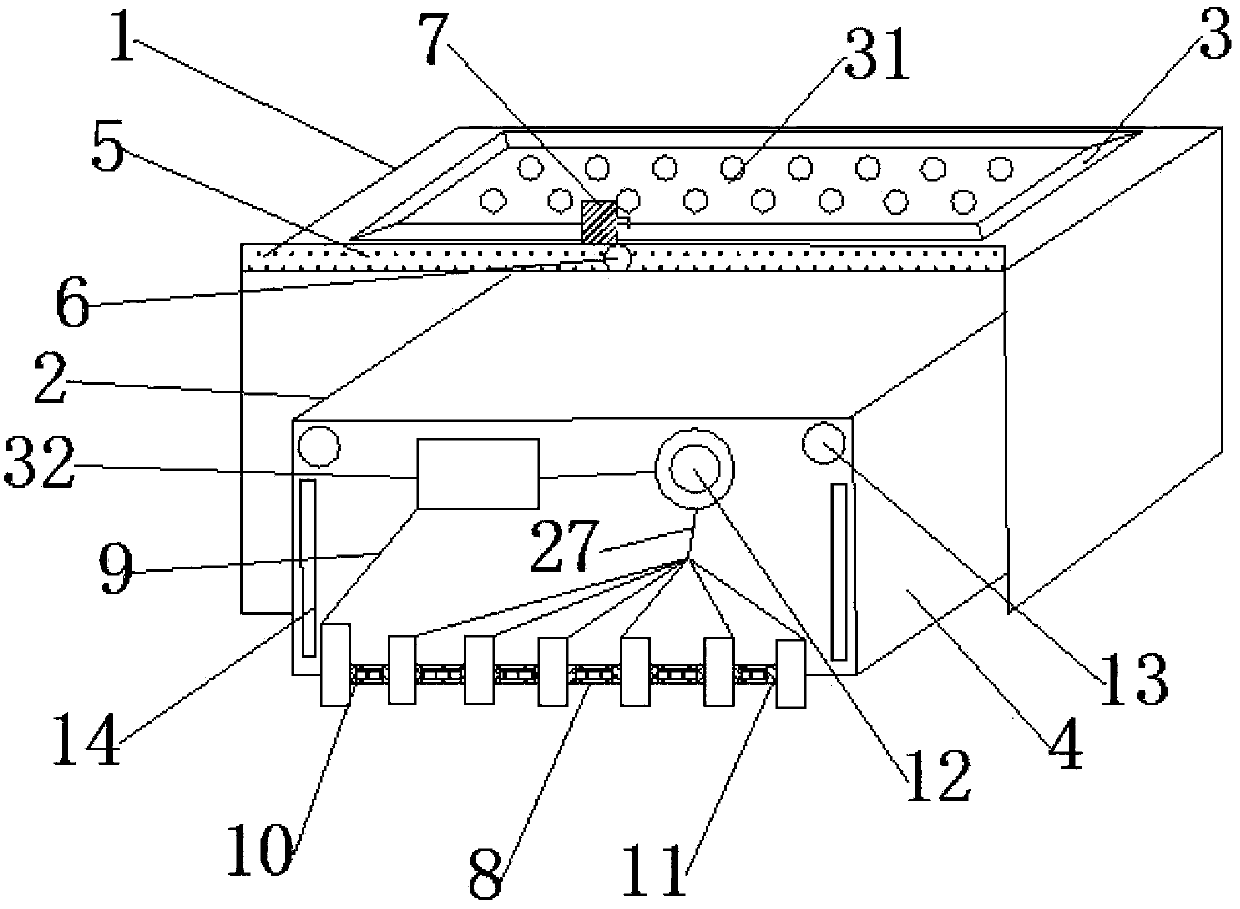
[0029] An optical splitter, comprising an optical splitter body, the optical splitter body includes a casing 1 and a box body 2, the casing 1 is slidably connected to the box body 2, the upper end of the box body 2 is provided with a panel 3, the box body A partition 4 is provided inside the body 2, and a hole 31 is provided on the panel 3; a shunt element 32 is provided inside the box body 2;

[0030] Further, the upper end of the housing 1 is provided with a chute 5, and the upper end of the chute 5 is provided with a scraper 7; the chute 5 is provided with a slide bar 6, and the slide bar 6 is located at the front and rear ends of the scraper 7 , the bottom end of the scraper 7 is attached to the shell 1; when the upper end of the shell 1 is contaminated with dirt, you only need to hold the slide bar 6 to move left and right, and the slide bar 6 will drive the scraper 7 along the slide The groove 5 moves left and right, and since the bottom end of the scraper 7 is attached ...


PUM


Abstract

The invention relates to an optical divider. The optical divider comprises a shell and a box body. The shell is slidably connected to the box body. The upper end of the box body is provided with a panel. A separation plate is arranged in the box body. The panel is provided with a hole. A shunt component is arranged in the box body. The upper end of the shell is provided with a chute. The upper endof the chute is provided with a scraper plate. A slide rod is arranged in the chute. The slide rod is located on the front and rear ends of the scraper plate. The bottom end of the scraper plate is attached to the shell. An optical divider body comprises an input adapter and an output adapter. The front panel of the box body is provided with an optical fiber inlet hole group and an optical fiberoutlet hole group. The input adapter is inserted through optical fiber inlet holes and is connected to the input end of the shunt component through an optical fiber with an empty tube. The optical divider body also comprises a simple optical fiber coupler, a low channel light filter, and a planar waveguide-type optical splitter body. The optical divider has advantages that the structure is compact; making is simple; cost is low; the optical divider splits light uniformly and can satisfy the transmission needs of different wavelengths.

Description

technical field [0001] The invention relates to optical fiber communication technology, in particular to an optical splitter. Background technique [0002] An optical splitter, also known as an optical splitter, is one of the important passive components in an optical fiber link. It is an optical fiber junction device with multiple input ports and multiple output ports. Existing optical splitters generally include a box body, a cover plate on the box body, and an optical splitter module. The box body is also provided with an input port and an output port. The input port passes through the optical fiber and the optical splitter module. The input ends are connected, and the output ports are connected with the output ends of the optical splitter module through optical fibers. Since the length of the optical fiber used in the cabinet needs to ensure a certain margin, the redundant optical fiber is often entwined with each other. The optical fiber is a common coated optical fibe...

Claims


Application Information

Patent Timeline
IPC IPC(8): G02B6/44
CPCG02B6/444
Inventor 尹红娟
Owner 尹红娟
Why Eureka
Try Eureka