Plane equipment cleaning robot

A technology for cleaning robots and equipment, applied to conveyors, mechanical conveyors, chemical instruments and methods, etc., can solve problems such as low production efficiency and difficult quality control

Pending Publication Date: 2019-03-29
KUNMING UNIV OF SCI & TECH
View PDF0 Cites 9 Cited by
  • Summary
  • Abstract
  • Description
  • Claims
  • Application Information

AI Technical Summary

Problems solved by technology

In most factories, this process is mostly done manually, its quality is difficult to control, and the production efficiency is low

Method used


Image

  • Plane equipment cleaning robot
  • Plane equipment cleaning robot
  • Plane equipment cleaning robot

Examples


Embodiment 1

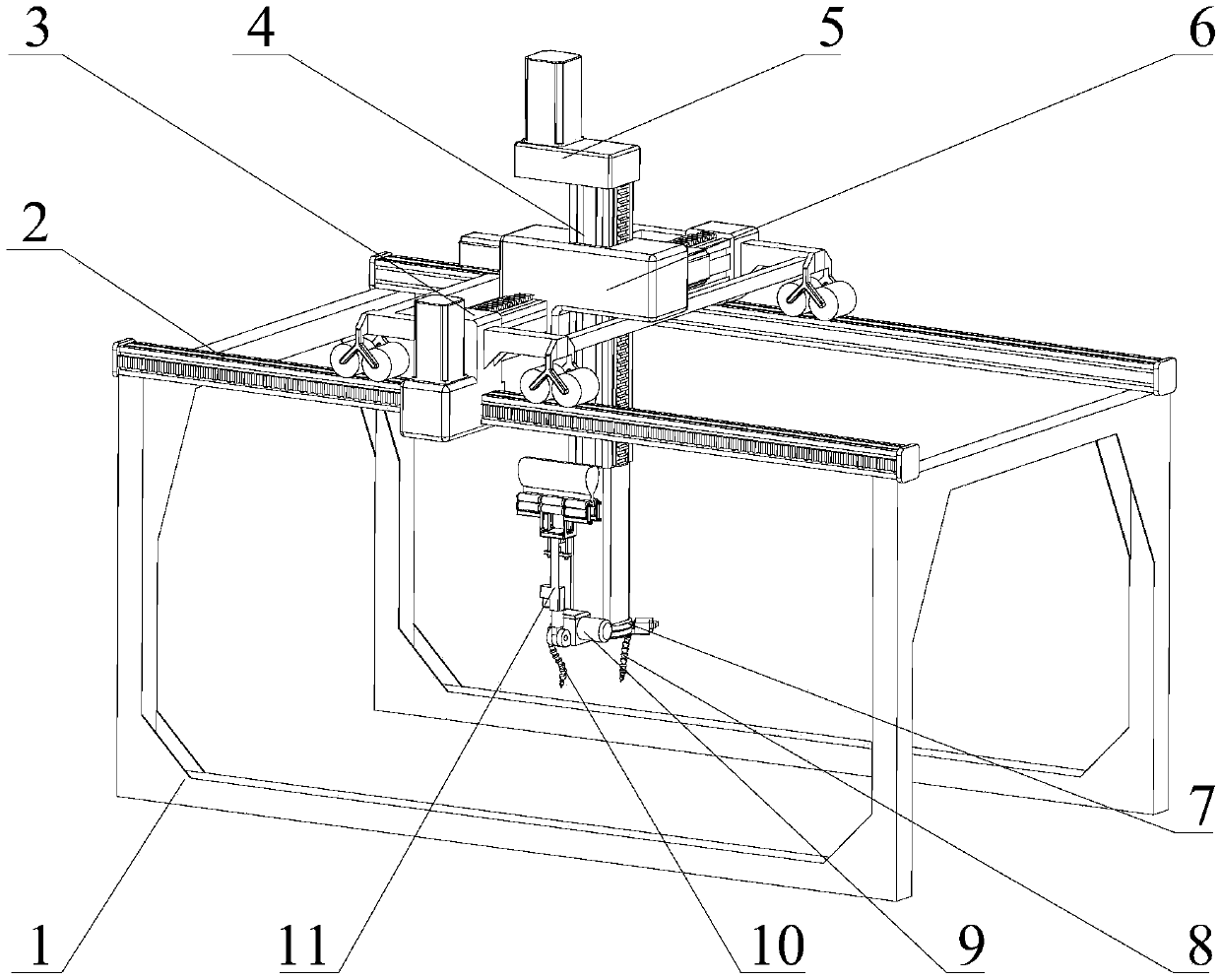
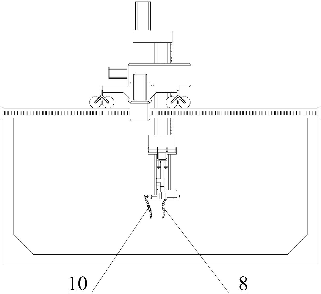
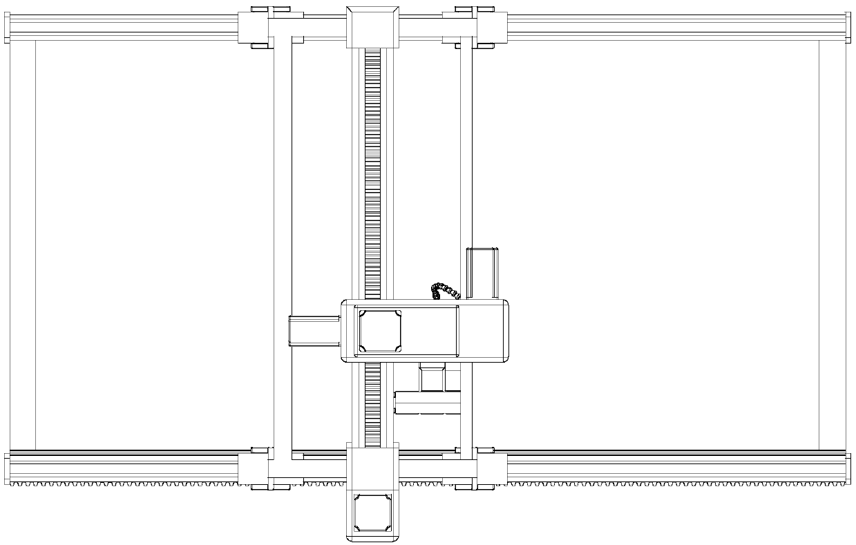
[0027] Embodiment 1: as Figure 1-12 As shown, a plane equipment cleaning robot includes a frame 1, an air jet liquid spray device I8, an air jet liquid spray device II10 and a Cartesian coordinate positioning mechanism; wherein the Cartesian coordinate positioning mechanism is fixed on the frame 1, and the air jet liquid spray device I8, The air-jet and liquid-jet device II10 is installed at the output end of the Cartesian coordinate positioning mechanism.

[0028] Further, the Cartesian coordinate positioning mechanism can be set to include X-guiding rail 2, Y-guiding rail 3, Z-guiding rail 4, reversing motor 5, horizontal positioning device 6, reversing flange 7, positioning motor I12-1, positioning Motor Ⅱ12-2, positioning motor Ⅲ12-3; among them, the X guide rail 2 is fixed on the frame 1 by bolts; the reducer I installed in the reducer I shell at the end of the Y guide rail 3 is fixed to the reducer by bolts Ⅰ The output shaft of the positioning motor Ⅰ12-1 on the casin...


PUM


Abstract

The invention discloses a plane equipment cleaning robot. The plane equipment cleaning robot comprises a machine frame, a jet liquid spraying device I, a jet liquid spraying device II and a rectangular coordinate positioning mechanism, wherein the rectangular coordinate positioning mechanism is fixed on the machine frame, the air injection liquid spraying device I, the air injection liquid spraying device II is arranged at an output end of the rectangular coordinate positioning mechanism. According to the plane equipment cleaning robot, the rectangular coordinate positioning mechanism can be used for carrying out linear movement in three directions, so that the output end can be positioned in space; through separate application of the two air injection liquid spraying devices, and one airinjection and one liquid spraying cleaning function can be realized at the same time; and wiping after cleaning and drying after wiping can be realized through a wiping device.

Description

technical field [0001] The invention relates to a plane equipment cleaning robot, which belongs to the field of mechanical equipment. Background technique [0002] At present, in the production and assembly of flat equipment, it is necessary to perform multiple cleaning processes on the product, including dust removal, spraying cleaning fluid, and drying. In most factories, this process is mostly done manually, the quality is difficult to control, and the production efficiency is low. Contents of the invention [0003] The invention provides a plane equipment cleaning robot, which is used to realize the air jet and liquid spray cleaning of the plane equipment and the drying after cleaning by means of mechanical control. [0004] The technical solution of the present invention is: a plane equipment cleaning robot, comprising a frame 1, an air-jet and liquid-spraying device I8, an air-jet and liquid-spraying device II10, and a Cartesian coordinate positioning mechanism; whe...

Claims


Application Information

Patent Timeline
Patent Type & Authority Applications(China)
IPC IPC(8): B08B3/02B65G35/00
CPCB08B3/024B65G35/00
Inventor 陈明方刘金鑫张永霞姚国一卢广龙高航周晓东臧家秀陈浩葛天佑李奇张凯翔赵佳媞李鹏宇
Owner KUNMING UNIV OF SCI & TECH
Why Eureka
Try Eureka