Hydraulic driving mechanism of toilet drain valve

A technology of driving mechanism and drain valve, which can be applied to flushing equipment with water tanks, water supply devices, buildings, etc., and can solve problems such as lack of anti-backflow function, high pressure, and lack of anti-backflow

Pending Publication Date: 2019-03-29
XIAMEN R&J PRECISION TECH CO LTD
View PDF0 Cites 1 Cited by
  • Summary
  • Abstract
  • Description
  • Claims
  • Application Information

AI Technical Summary

Problems solved by technology

[0002] Existing toilet drainage control mechanisms have two types: direct-press type and indirect-drive type, among which the direct-press type drain valve requires a relatively high pressure (>8N, even greater than 25N when the water level is high) and does not have the anti-back

Method used


Image

  • Hydraulic driving mechanism of toilet drain valve
  • Hydraulic driving mechanism of toilet drain valve
  • Hydraulic driving mechanism of toilet drain valve

Examples


Embodiment Construction

[0023] To further illustrate the various embodiments, the present invention is provided with accompanying drawings. These drawings are a part of the disclosure of the present invention, which are mainly used to illustrate the embodiments, and can be combined with related descriptions in the specification to explain the operating principles of the embodiments. With reference to these contents, those skilled in the art should understand other possible implementations and advantages of the present invention.

[0024] The present invention will be further described in conjunction with the accompanying drawings and specific embodiments.

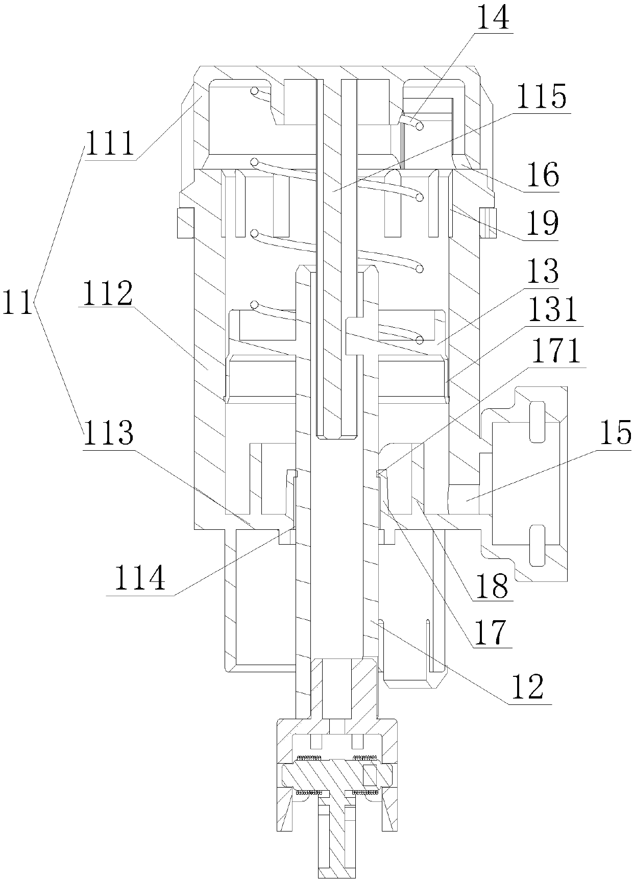
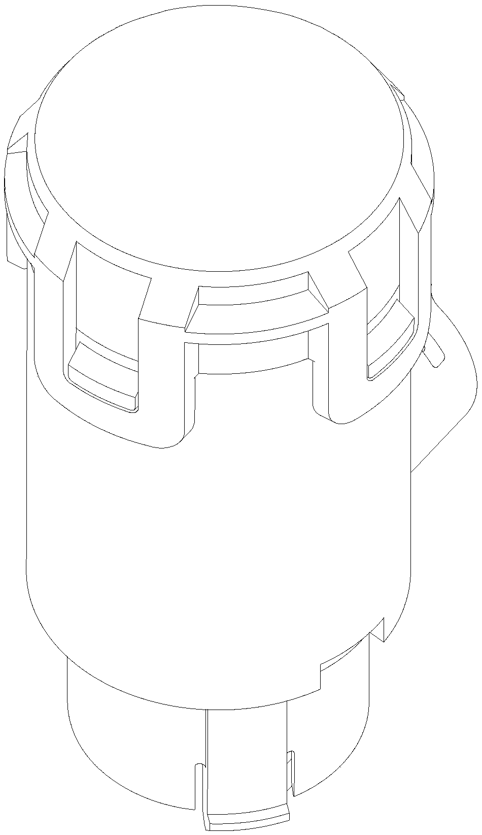
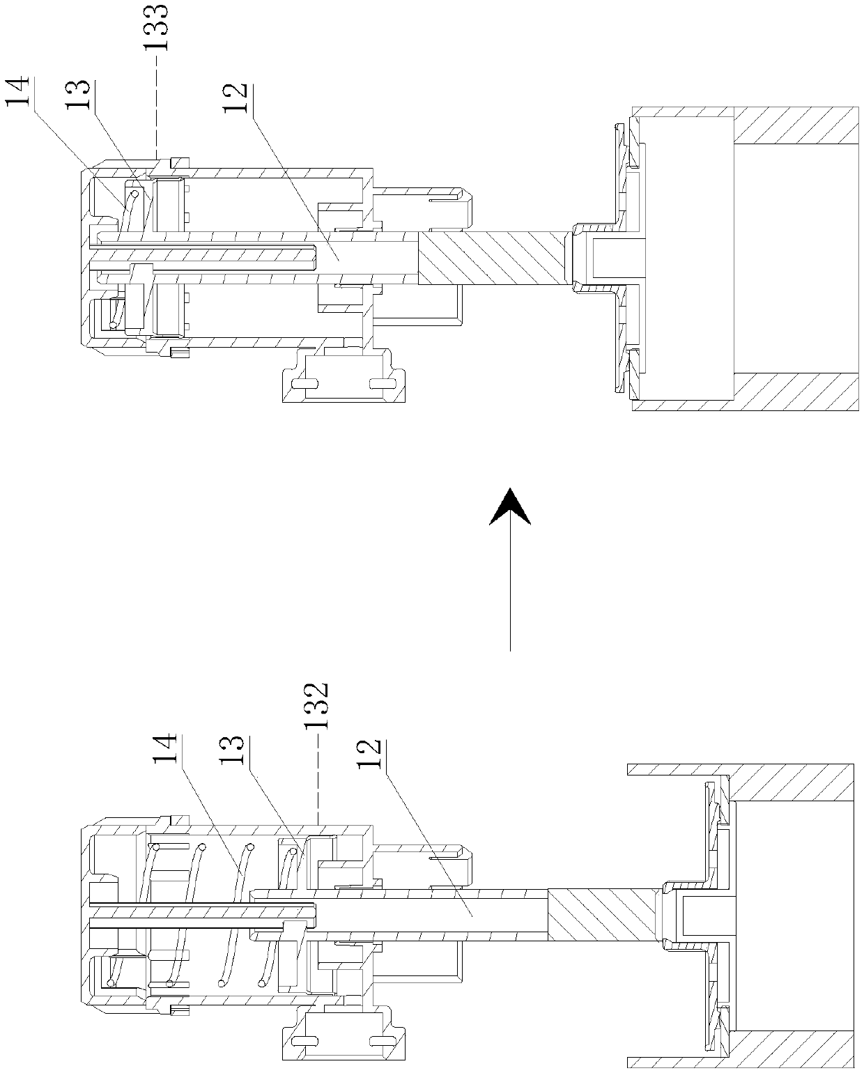
[0025] Such as Figure 1~2 As shown, the embodiment of the present invention provides a hydraulic drive mechanism of the toilet drain valve, the hydraulic drive mechanism is used to drive the opening or closing of the valve port of the toilet drain valve, and then control the water in the toilet water tank from the drain valve valve discharge. ...


PUM


Abstract

The invention relates to a hydraulic driving mechanism of a toilet drain valve, and relates to the technical field of toilet drain valves. The hydraulic driving mechanism comprises a hydraulic cylinder, a piston rod, a piston and an elastic element, the elastic element exerts acting force, in a first direction, on the piston, the piston is limited at a first position under the acting force of theelastic element, a cylinder body is further provided with an inlet and an outlet, the inlet is formed so that liquid can enter the cylinder body to push the piston to move in a second direction from the first position, the piston moves to a second position under the effect of pressure of the liquid in the cylinder body, the outlet is formed in the end, in the second direction, of the second position of the cylinder body, the piston is connected with the piston rod which penetrates out of the cylinder body, and the piston drives the piston rod to conduct reciprocating motion under reciprocatingmotion of the first position and the second position. The hydraulic driving mechanism can realize an anti-backflow function, and prevents dirt on a pot face from flowing back into a water tank when atoilet is blocked.

Description

technical field [0001] The invention relates to the technical field of a toilet drain valve, in particular to a hydraulic drive mechanism for a toilet drain valve. Background technique [0002] Existing toilet drainage control mechanisms have two types: direct-press type and indirect-drive type, among which the direct-press type drain valve requires a relatively high pressure (>8N, even greater than 25N when the water level is high) and does not have the anti-backflow function. And the drain valve of indirect drive type, driving structure is complicated, and also does not possess anti-backflow function, when toilet block, the dirt on pot surface flows back into water tank through the drain outlet of toilet pipeline, drain valve. Contents of the invention [0003] In view of the above problems, the present invention aims to provide a hydraulic drive mechanism for the toilet drain valve, which uses hydraulic pressure as the driving force and has a large driving force. The...

Claims


Application Information

Patent Timeline
IPC IPC(8): E03D1/34
CPCE03D1/34
Inventor 胡诗明唐亚平
Owner XIAMEN R&J PRECISION TECH CO LTD
Why Eureka
Try Eureka