Valve structure and electromagnetic valve device
A solenoid valve and valve technology, which is applied in the direction of valve device, valve housing structure, valve operation/release device, etc., can solve the problems of coil magnetic instability, high use cost, and large power consumption, etc., and achieve sensitive response and reduce The effect of increasing the usage amount and the reaction area
- Summary
- Abstract
- Description
- Claims
- Application Information
AI Technical Summary
Problems solved by technology
Method used
Image
Examples
Embodiment 1
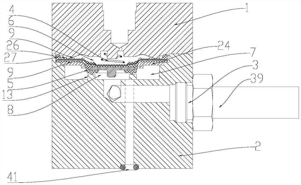
[0043] Such as figure 1 As shown, the present embodiment discloses a valve structure, which includes: a valve body, an inner cavity is formed in the valve body, in order to form the inner cavity, the structure of the valve body is not specifically limited, of course, for the convenience of processing, the The valve body is designed as several detachably connected or fixedly connected parts. In this embodiment, the valve body is designed as two pieces, namely the upper valve body 1 and the lower valve body 2. For processing and installation, generally It is designed that the upper valve body 1 and the lower valve body 2 are connected by bolts, and the upper valve body 1 and the lower valve body 2 enclose the inner cavity; Elastic diaphragm 5 is arranged, and described elastic diaphragm 5 generally selects elastic material to make, and in order to increase its certain rigidity, can add cord and / or stiffener plate etc. in elastic material, as described elastic material is rubber ...
Embodiment 2
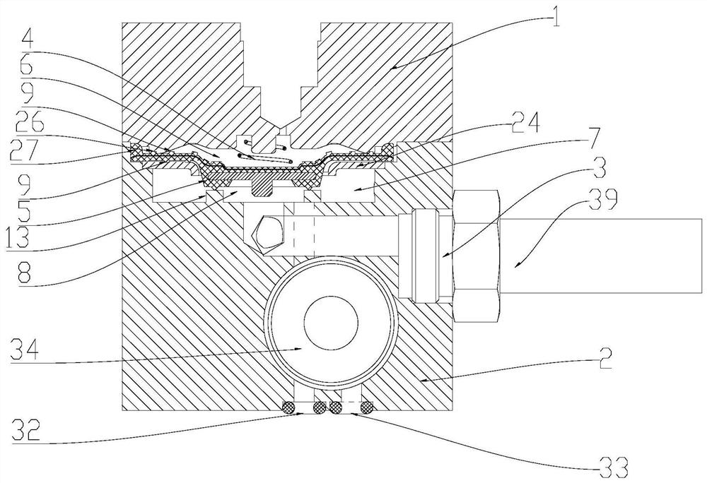
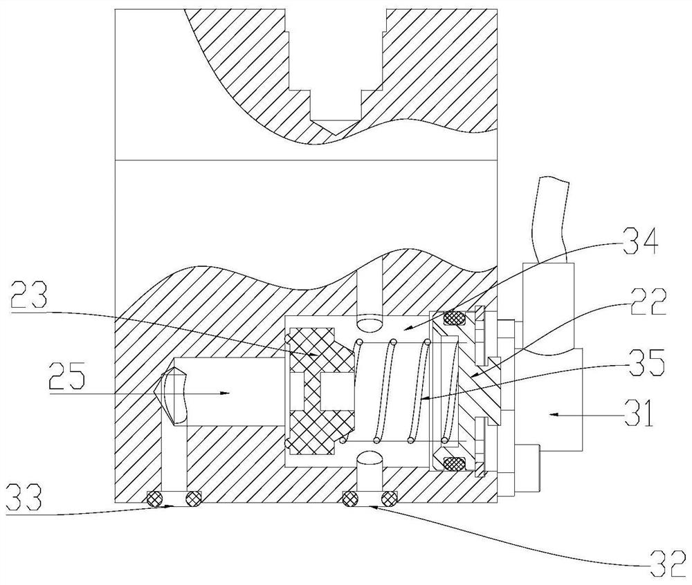
[0050] Such as figure 2 with image 3 As shown, this embodiment discloses a valve structure, which is an improvement on the basis of Embodiment 1. The specific improvements are as follows: the inlets are set to two, respectively the first inlet 32 and the second inlet 32. Two inlet ports 33; at the same time, a flow control valve chamber 34 is provided in the lower valve body 2, and a flow control valve assembly is arranged in the flow control valve chamber 34; the first inlet port 32 passes through the channel and The B chamber 7 communicates; the second inlet port 33 communicates with the B chamber 7 through the flow control valve chamber 34. At this time, the fluid passing through the second inlet port 33 is in the flow control Under the control of the valve assembly, it enters the B cavity 7 as required. The above arrangement can realize the use of one valve structure, and through the control of the flow control valve assembly, fluids of two pressures can be discharge...
Embodiment 3
[0056] Such as Figure 4-8 As shown, this embodiment discloses a solenoid valve device, which is an improvement on the basis of Embodiment 2, and the specific improvements are as follows: it also includes an electromagnetic assembly arranged on the upper valve body 1; the upper valve The body 1 is provided with an installation cavity 36, the electromagnetic assembly and the wall of the installation cavity 36 are enclosed to form a D cavity 10 and an E cavity 37, the D cavity 10 communicates with the A cavity 6, and the D cavity The chamber 10 communicates with or cuts off the atmosphere, and the E chamber 37 communicates with the B chamber 7; the electromagnetic assembly is used to switch the communication or isolation state between the D chamber 10 and the E chamber 37, and the electromagnetic assembly is powered on. , the D chamber 10 communicates with the E chamber 37, and further, the D chamber 10 communicates with the B chamber 7 through the E chamber 37. At this time, th...
PUM
 Abstract
Description
Claims
Application Information
 - R&D
- Intellectual Property
- Life Sciences
- Materials
- Tech Scout
- Unparalleled Data Quality
- Higher Quality Content
- 60% Fewer Hallucinations
Browse by: Latest US Patents, China's latest patents, Technical Efficacy Thesaurus, Application Domain, Technology Topic, Popular Technical Reports.
© 2025 PatSnap. All rights reserved.Legal|Privacy policy|Modern Slavery Act Transparency Statement|Sitemap|About US| Contact US: help@patsnap.com


