Kitchen cleaning tank

A technology for cleaning tanks and kitchens, applied in the field of kitchen equipment, which can solve the problems of large space occupation, rapid water output from the faucet, and water splashing on the countertop, etc., and achieve the effects of simplified structure, convenient water use, and saving operating space

Inactive Publication Date: 2016-12-14
韦振婕
View PDF6 Cites 1 Cited by
  • Summary
  • Abstract
  • Description
  • Claims
  • Application Information

AI Technical Summary

Problems solved by technology

However, in the process of taking water from the faucet, due to the poor control of the size of the valve and the different water pressure of each floor, the water output is often violent when the faucet is turned on, and the water splashes on the table.
On the other hand, in order to prevent water from overflowing to the countertop, overflow holes are provided on each basin of the double-bowl sink, and each overflow hole is connected to the drain pipe through a pipe, which makes the structure of the double-bowl sink complex and takes up a lot of space

Method used


Image

  • Kitchen cleaning tank
  • Kitchen cleaning tank

Examples


Embodiment 1

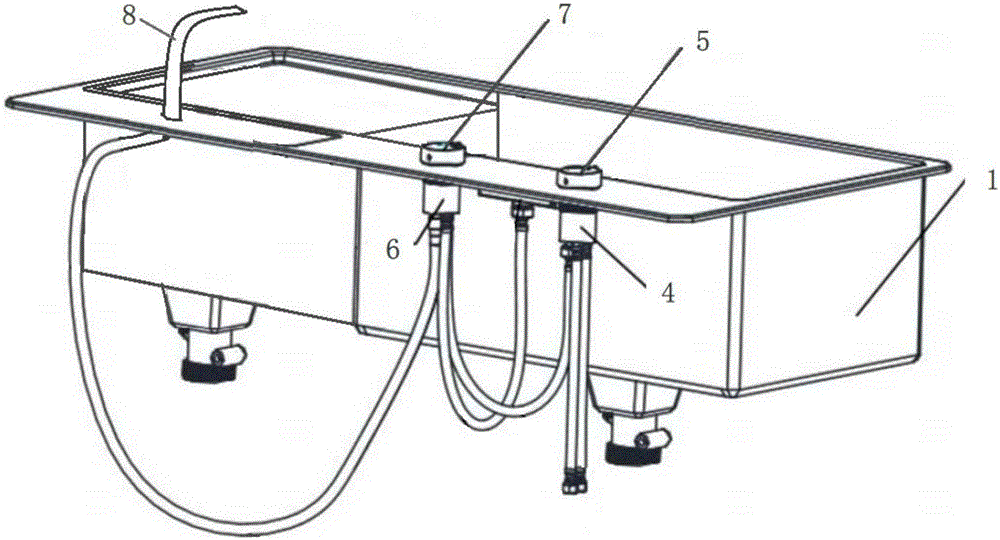
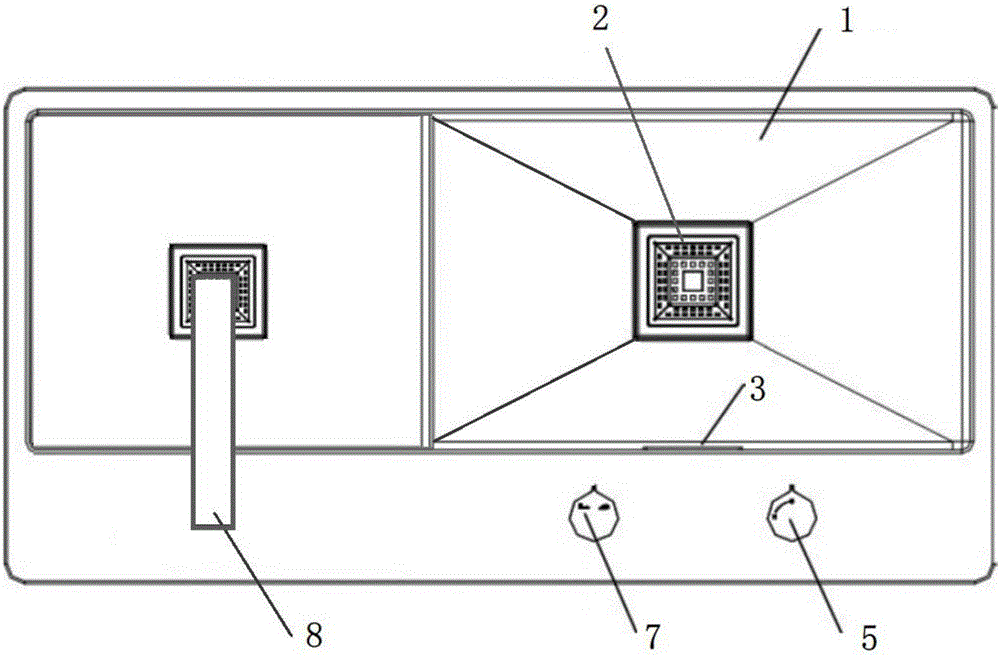
[0021] This embodiment provides a kitchen cleaning tank, which includes a sink main body 1, a drain plug 2, a hot and cold water conversion device, and a faucet device. The hot and cold water conversion device is installed on the sink main body 1, and the faucet device and The cold and hot water conversion device is connected, and the faucet device includes a waterfall-type outlet faucet 3 embedded in the tank wall of the sink body 1. The sink body 1 has two cleaning chambers separated by partitions, each cleaning A drain is provided at the bottom of the cavity, and the drain plug 2 cooperates with the drain, and an overflow hole is provided on the tank wall of one of the cleaning chambers, and the overflow hole is higher than the top surface of the partition.

[0022] The hot and cold water conversion device includes: a hot and cold water valve core main body 4 that is connected to the hot and cold water inlet pipe at one end and connected to the waterfall-type outlet faucet a...

Embodiment 2

[0028] This embodiment provides a kitchen cleaning tank, which includes a sink main body 1, a drain plug 2, a hot and cold water conversion device, and a faucet device. The hot and cold water conversion device is installed on the sink main body 1, and the faucet device and The cold and hot water conversion device is connected, and the faucet device includes a waterfall-type outlet faucet 3 embedded in the tank wall of the sink body 1. The sink body 1 has two cleaning chambers separated by partitions, each cleaning A drain is provided at the bottom of the cavity, and the drain plug 2 cooperates with the drain, and an overflow hole is provided on the tank wall of one of the cleaning chambers, and the overflow hole is higher than the top surface of the partition.

[0029] The hot and cold water conversion device includes: a hot and cold water valve core main body 4 that is connected to the hot and cold water inlet pipe at one end and connected to the waterfall-type outlet faucet a...


PUM


Abstract

The invention relates to kitchen equipment, in particular to a kitchen cleaning tank which comprises a water tank body, a leak stopper, a hot and cold water switching device and a tap device. The hot and cold water switching device is mounted on the water tank body, the tap device is communicated with the hot and cold water switching device and comprises a waterfall outflow tap embedded into a wall of the water tank body, the water tank body is provided with two cleaning cavities separated by a partition plate, a water outlet is formed in the tank bottom of each cleaning cavity, the leak stopper is matched with the water outlet, and an overflow hole is formed in the tank wall of one cleaning cavity and higher than the top of the partition plate. As the tap is arranged on the wall of the water tank body, the space of a table top of the water tank body will not be occupied. Besides, the two cleaning cavities share one overflow hole, the structure of the cleaning tank is simplified and more operation space is saved for users.

Description

technical field [0001] The invention relates to kitchen equipment, in particular to a kitchen cleaning tank. Background technique [0002] The kitchen sink (that is, the sink) is the heart of the kitchen. According to statistics, among all kinds of appliances in the kitchen, the sink has the highest utilization rate. In the preparation and cleaning work before and after meals, more than 65% of the time is directly related to the sink, so it is very important to choose a beautiful, good-performance, clean sink to build a comfortable and warm kitchen. [0003] According to the material, the sink can be divided into cast iron enamel, ceramic, stainless steel, artificial stone, steel plate enamel, acrylic and crystal stone sink, etc. According to the style, it can be divided into single basin, double basin, large and small double basin and special-shaped double basin. The sinks currently on the market do not only refer to the sink itself that holds water, but also include fauc...

Claims


Application Information

Patent Timeline
Patent Type & Authority Applications(China)
IPC IPC(8): E03C1/182E03C1/186E03C1/04E03C1/044A47J47/20
CPCA47J47/20E03C1/0402E03C1/0404E03C1/044E03C1/182E03C1/186
Inventor 韦振婕
Owner 韦振婕
Why Eureka
Try Eureka