
Automatic demounting robot for frame-supporting column formwork for building construction

A technology for dismantling robots and building construction. It is applied in the direction of construction, building structure, and on-site preparation of building components. It can solve the problems of high work efficiency, low labor intensity, and low demolition efficiency, and achieve high work efficiency and low labor intensity. Small, efficient demolition effect

Active Publication Date: 2019-03-29
太仓臻溢科技有限公司
View PDF5 Cites 2 Cited by
  • Summary
  • Abstract
  • Description
  • Claims
  • Application Information

AI Technical Summary

Problems solved by technology

[0003] In order to solve the above problems, the present invention provides an automatic removal robot for frame and pillar formwork for building construction, which can solve the existing problems in the removal process of the existing frame and pillar formwork that the formwork needs to be removed manually with the help of tools, and the bonding between the concrete and the formwork can be solved. It is relatively tight, and it is necessary to manually use a chisel to separate the formwork from the concrete. Manual use of a chisel is easy to cause the concrete surface to collapse, and the labor intensity is high, and the demolition efficiency is low. It can realize the function of automatically and efficiently dismantling the frame pillar formwork without manual labor operation, will not collapse the concrete, and has the advantages of low labor intensity and high work efficiency

Method used


Image

  • Automatic demounting robot for frame-supporting column formwork for building construction
  • Automatic demounting robot for frame-supporting column formwork for building construction
  • Automatic demounting robot for frame-supporting column formwork for building construction

Examples


Embodiment Construction

[0024] In order to make the technical means, creative features, goals and effects achieved by the present invention easy to understand, the present invention will be further described below in conjunction with specific illustrations.

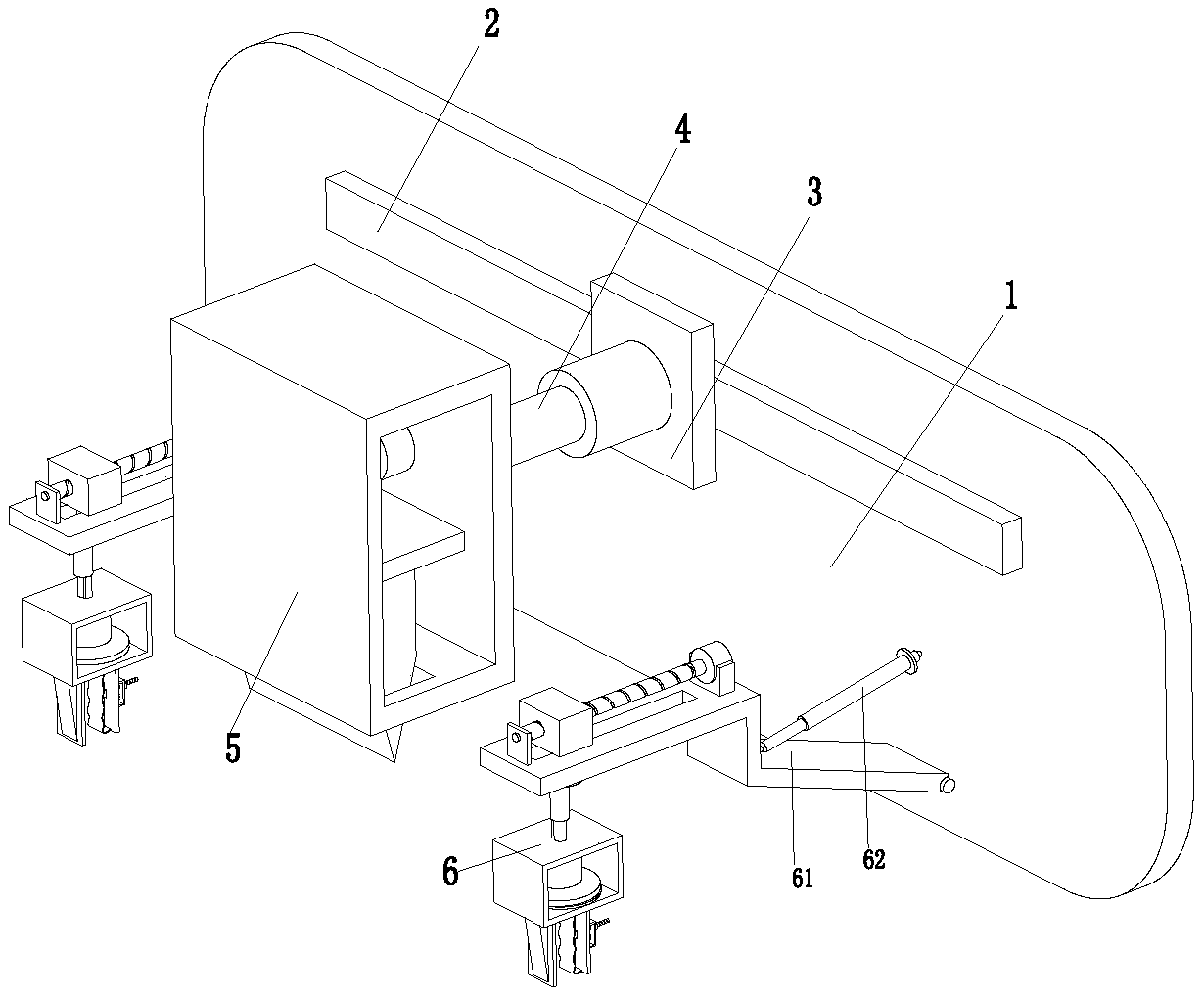
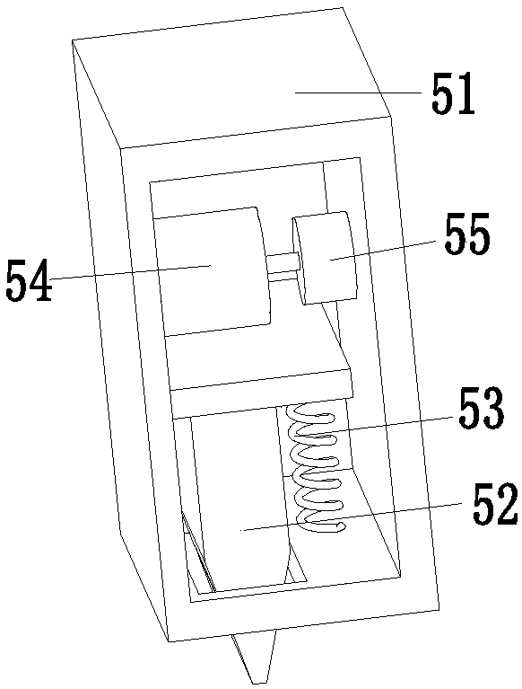
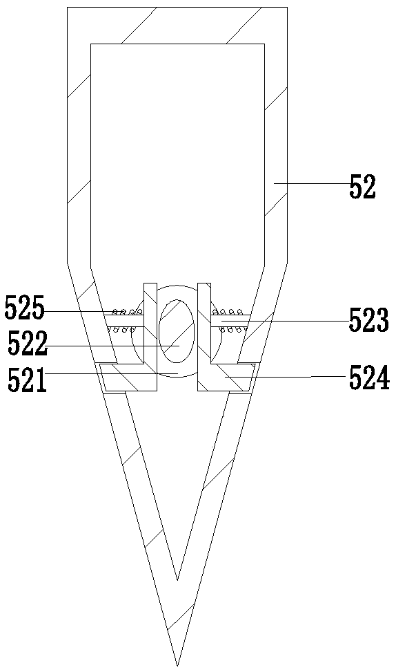
[0025] Such as Figure 1 to Figure 4 As shown, a robot for automatically dismantling frame and pillar templates for building construction includes a mounting plate 1, a mobile electric slider 2 is installed on the side wall of the mounting plate 1, a mobile sliding plate 3 is installed on the mobile electric sliding block 2, and a mobile sliding plate 3 The mobile telescopic cylinder 4 is installed on the top, and the top of the mobile telescopic cylinder 4 is equipped with an executive chisel device 5. The left and right sides of the installation plate 1 are symmetrically equipped with an executive removal device 6. The mobile electric slider 2 and the mobile electric slider 2 are controlled. Execute the chisel device 5 to perform movement and ...


PUM


Abstract

The invention relates to an automatic demounting robot for a frame-supporting column formwork for building construction. The automatic demounting robot comprises a mounting plate, a movable electric sliding block is mounted on the side wall of the mounting plate, a movable sliding plate is mounted on the movable electric sliding block, a movable telescopic air cylinder is mounted on the movable sliding plate, a cutting executing device is mounted at the top end of the movable telescopic air cylinder, and demounting executing devices are symmetrically arranged on the left side and the right side of the mounting plate. According to the automatic demounting robot, the problems that in the demounting process of an existing frame-supporting column formwork, the formwork needs to be manually demounted with the help of tools, concrete and the formwork are bonded tightly, the formwork and the concrete needs to be manually separated through a chisel, the surface of the concrete is likely to bemoldered when the chisel is manually used, the labor intensity is high, and the demounting efficiency is low can be solved, the function of automatically and efficiently demounting the frame-supporting column formwork can be achieved, manual operation is not needed, the concrete cannot be moldered, and the advantages of being low in labor intensity, high in work efficiency and the like are achieved.

Description

technical field [0001] The invention relates to the technical field of building frame pillars, in particular to a robot for automatically removing frame pillar templates for building construction. Background technique [0002] During the building construction process, due to the functional requirements of the building, the large space in the lower part and the vertical components in the upper part cannot be directly and continuously connected to the ground, but are connected to the vertical components in the lower part through a horizontal conversion structure. When the transfer beam is arranged to support the upper shear wall, the transfer beam is called the frame beam, and the column supporting the frame beam is called the frame pillar. The construction of the frame pillar requires a steel cage as the foundation, and concrete is used for pouring. The formwork needs to be used for protection. After the frame pillar is formed, the formwork needs to be removed. However, in th...

Claims


Application Information

Patent Timeline
Patent Type & Authority Applications(China)
IPC IPC(8): E04G19/00
CPCE04G19/00
Inventor 冯露晨
Owner 太仓臻溢科技有限公司
Learn More