
Push rod transposition mechanism

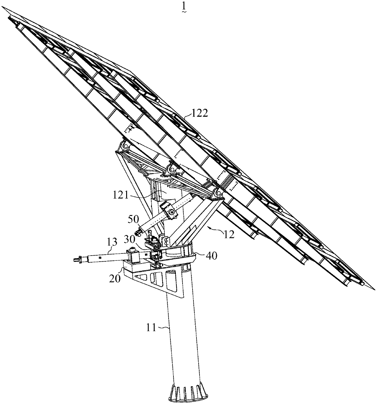
A push rod and guide rod technology, applied in the field of heliostat frames, can solve the problems of inability to track the sun all-weather, small rotation range of the connecting seat, etc., and achieve the effect of expanding the rotation range and the large rotation range.

Pending Publication Date: 2019-03-29
龙岩智康太阳能科技有限公司
View PDF0 Cites 1 Cited by
  • Summary
  • Abstract
  • Description
  • Claims
  • Application Information

AI Technical Summary

Problems solved by technology

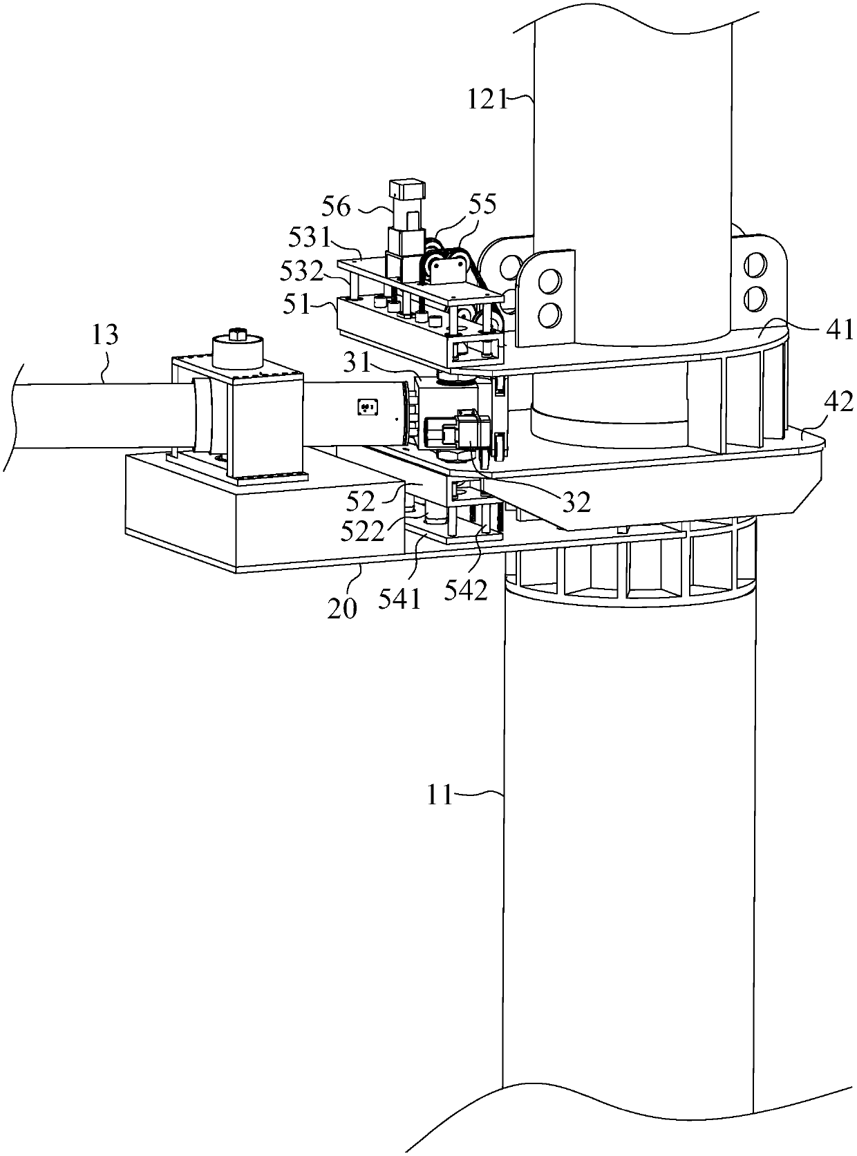
[0003] The purpose of the present invention is to provide a push rod transposition mechanism, aiming to solve the problem that the push rod in the prior art cannot cross the connecting line between the mounting seat and the rotation center of the connecting seat, which causes the rotation range of the connecting seat to be too small and cannot be used all-weather. Technical problems with tracking the sun

Method used


Image

  • Push rod transposition mechanism
  • Push rod transposition mechanism
  • Push rod transposition mechanism

Examples


Embodiment Construction

[0049] Embodiments of the present invention are described in detail below, examples of which are in the appended figure 1 to attach Figure 8 , wherein the same or similar reference numerals represent the same or similar elements or elements having the same or similar functions throughout. Attached below by reference figure 1 to attach Figure 8 The described embodiments are exemplary and are intended to explain the present invention, but should not be construed as limiting the present invention.

[0050] In describing the present invention, it should be understood that the terms "length", "width", "upper", "lower", "front", "rear", "left", "right", "vertical", The orientation or positional relationship indicated by "horizontal", "top", "bottom", "inner", "outer", etc. are based on the orientation or positional relationship shown in the drawings, and are only for the convenience of describing the present invention and simplifying the description, rather than Nothing indica...


PUM


Abstract

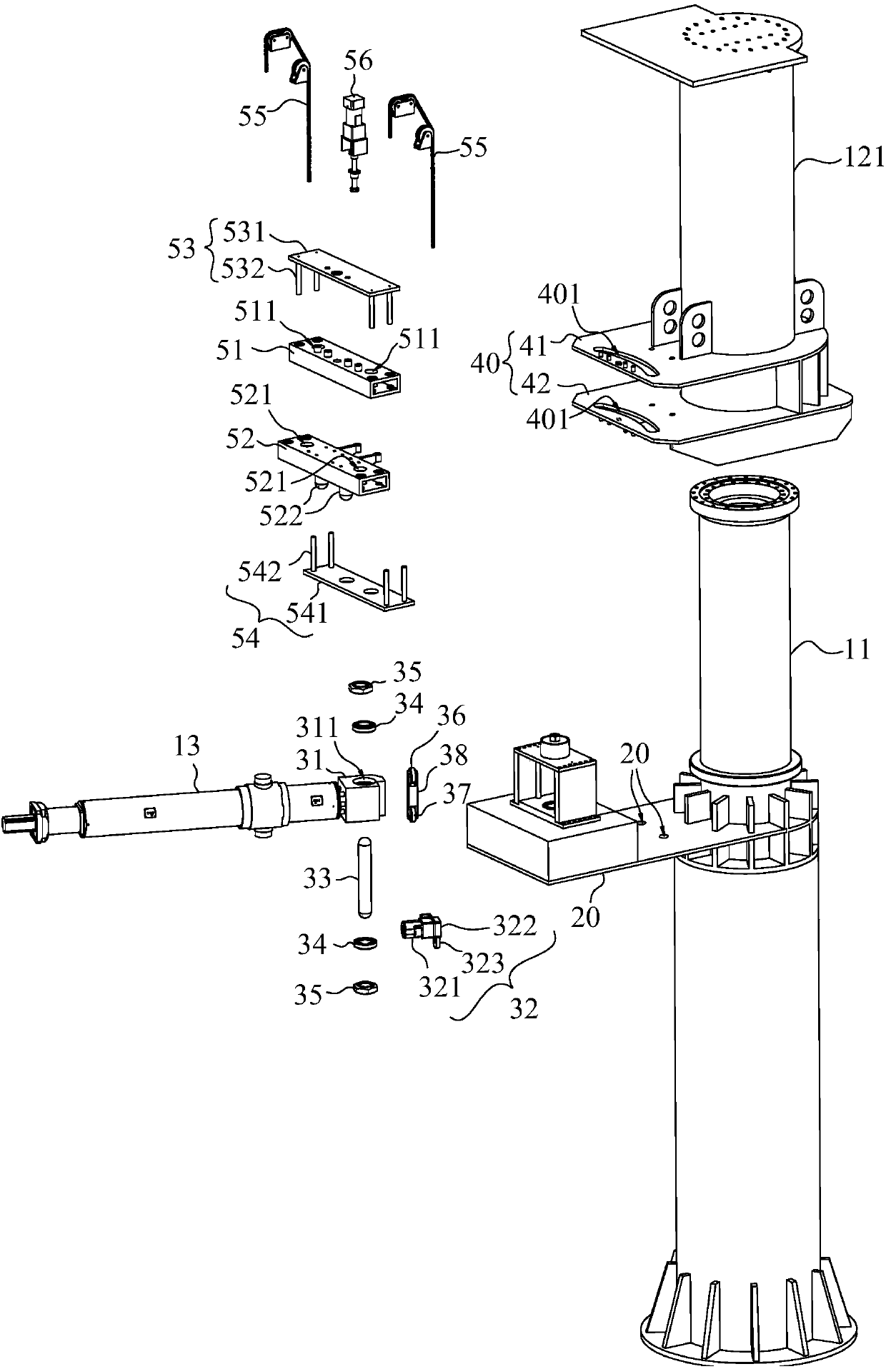
The invention belongs to the technical field of heliostat brackets, and particularly relates to a push rod transposition mechanism. The push rod transposition mechanism is used for switching positionsof a push rod and comprises a mounting seat, a connecting seat, the push rod and an output joint; the mounting seat is arranged on a vertical column, and the push rod is rotatably arranged on the mounting seat; an arc-shaped sliding groove is formed in the connecting seat, and the connecting seat is arranged on a rotating frame; the output joint comprises a joint body, a driving wheel set and a sliding piece; the joint body is fixed to the tail end of the push rod, and the sliding piece is connected with the joint body and stretches into the arc-shaped sliding groove; and the driving wheel set is fixed to the joint body, and the driving wheel set rolls on the connecting seat along the edge of the arc-shaped sliding groove and drives the sliding piece to move along the arc-shaped sliding groove. The output joint moves from one side of a connecting line to the other side to cross the connecting line of the rotating centers of the mounting seat and the connecting seat, the push rod can continue to adjust rotation of the rotating frame, thus the driving range of the push rod is doubled, the range of rotating of the connecting seat around the rotating center is doubled, and thus the heliostat brackets can better adapt to the positions where large-range rotating is needed.

Description

technical field [0001] The invention belongs to the technical field of heliostat frames, in particular to a push rod transposition mechanism. Background technique [0002] In the solar thermal power generation system, multiple heliostat frames are used to reflect sunlight to the receiver. The heliostat frame includes a column and a turret. The turret is equipped with multiple reflectors, and the lower part of the turret is equipped with a sleeve. , the sleeve is sleeved on the column and rotates around the column, and the turret is assisted to track the sun by rotating the turret around the column. The heliostat frame is distributed around the receiver. In order to make the reflector reflect sunlight all-weather, set the push rod to push the turret to change the orientation of the turret. In different positions, the turret needs to rotate in different ranges to track the sun all-weather . On the heliostat frame, the turret is driven to rotate through the push rod. Specific...

Claims


Application Information

Patent Timeline
IPC IPC(8): F24S30/422
CPCY02E10/47
Inventor 兰宝胜黄晓龙
Owner 龙岩智康太阳能科技有限公司
Features
  • Generate Ideas
  • Intellectual Property
  • Life Sciences
  • Materials
  • Tech Scout
  • Unparalleled Data Quality
  • Higher Quality Content
  • 60% Fewer Hallucinations
Learn More