Al technical title is built by PatSnap Al team. It summarizes the technical point description of the patent document.
A tracking mechanism, solar technology, applied in the direction of solar thermal energy, solar thermal power generation, solar thermal collectors, etc., can solve the problems of complex control process, increasing the power of the terminal drive device, complex mechanism, etc.
Inactive Publication Date: 2009-08-05
JIANGSU POLYTECHNIC UNIVERSITY
View PDF2 Cites 9 Cited by
Summary
Abstract
Description
Claims
Application Information
AI Technical Summary
This helps you quickly interpret patents by identifying the three key elements:
Problems solved by technology
Method used
Benefits of technology
Problems solved by technology
[0004] Chinese invention patent documents [200610088374.9], [200610044529.9], [200610088177.7], [200610088118.X] respectively disclose four kinds of tracking devices for solar photovoltaic power generation. The weight of the end drive system must be borne by the end drive that tracks the other angular direction, which inevitably increases the power of the end drive while being bulky and wasting material and energy
[0005] The document "Research on Sun Tracking Device Based on Parallel Spherical Mechanism" (Zhang Shunxin, Song Kaifeng, etc., "Journal of Hebei University of Technology", 2003, 32(6): 44-48) introduces the two-axis tracking based on three-degree-of-freedom parallel spherical mechanism The device can realize the complete tracking of the sun's movement and greatly improve the receiving efficiency of the receiver. It has the characteristics of high rigidity, large working space, and compact structure. quite complicated
Method used
Image
Click on the blue label to locate the original text in one second.
Reading with bidirectional positioning of images and text.
Examples
Embodiment Construction
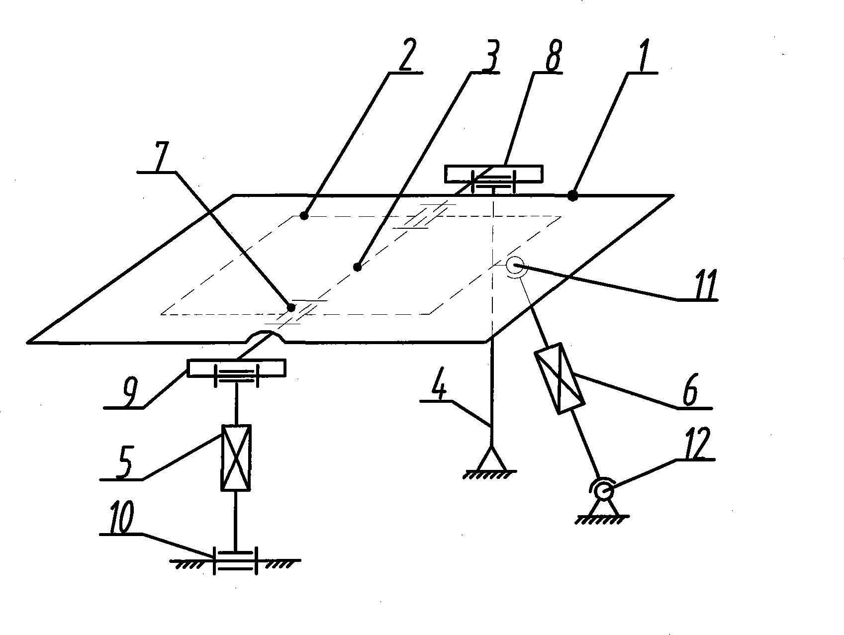
[0011] The technology of the present invention will be further described below by means of accompanying drawings and examples.
[0012] attached figure 1 It is a structural schematic diagram of the present invention, which is composed of a solar cell module flat plate 1, a flat support frame 2, a support shaft 3, a fixed support frame 4, linear drives 5, 6, rotating hinges 8, 9, 10, ball hinges 11, 12, etc. , which is characterized in that the plate support frame 2 used to fix the battery assembly plate 1 is sleeved on the support shaft 3 with a rotary hinge 7, and the two ends of the support shaft 3 are connected to the fixed support frame 4 and the linear drive 5 respectively with the rotary hinges 8 and 9 respectively. The other end of the linear drive 5 is connected with the ground frame 0 with a rotary hinge 10. The axes of these three rotary hinges 8, 9, 10 must be parallel to the rotary hinges 8, 10 on the support shaft 3. The axis of 9 is vertical; One side end of fla...
PUM
Abstract
The invention discloses a parallel type solar two-shaft tracking mechanism which comprises a solar battery component flat plate (1), a flat plate supporting framework (2), a support shaft (3), a fixed support frame (4), linear drivers (5, 6), rotation hinges (8, 9, 10), ball hinges (11, 12), and the like. The parallel type solar two-shaft tracking mechanism is characterized in that the flat plate supporting framework (2) used for fixing the battery component flat plate (1) is sleeved on the support shaft (3) through the rotation hinge (7), both ends of the support shaft (3) are respectively connected with the extending ends of the fixed support frame (4) and the extending end of the linear driver (5) through the rotation hinges (8, 9), the other end of the linear driver (5) is connected with a ground stand (0) through a rotation pair (10), and the axial lines of the three rotation hinges (8, 9, 10) are arranged in parallel and are vertical to the axial lines of the rotation hinges (8, 9) on the support shaft (3); one side end of the flat plate supporting framework (2) is connected with the extending end of the other linear driver (6) through the ball hinge (11), and the other end of the linear driver (6) is connected with the ground stand (0) through the other ball hinge (12). The mechanism has simple structure, controls decoupling, and is easy to manufacture and process. When the two linear drivers (5, 6) carries out the driving function, the mechanism can automatically track so as to realize the variation rule of sunlight azimuth angles and altitude angles.
Description
technical field [0001] The invention relates to a parallel solar two-axis tracking mechanism, in particular to provide a new parallel solar two-degree-of-freedom two-axis tracking mechanism for solar tracking technology and the like. Background technique [0002] As an important part of new energy, solar energy is increasingly favored by people, and the use of sun tracking technology can greatly improve the receiving efficiency of solar energy. The single-axis solar tracker can complete automatic tracking in the east-west direction, while the north-south direction can be manually adjusted, and the heat receiving rate of the receiver can be increased by 15%. The single-axis solar tracker has a simple structure, low production cost, and a fixed solar receiving efficiency ratio The conventional devices have been greatly improved, but relatively speaking, the solar energy reception rate is still low. In recent years, the two-axis tracking technology has become a hot spot in res...
Claims
Application Information
Patent Timeline
Application Date:The date an application was filed.
Publication Date:The date a patent or application was officially published.
First Publication Date:The earliest publication date of a patent with the same application number.
Issue Date:Publication date of the patent grant document.
PCT Entry Date:The Entry date of PCT National Phase.
Estimated Expiry Date:The statutory expiry date of a patent right according to the Patent Law, and it is the longest term of protection that the patent right can achieve without the termination of the patent right due to other reasons(Term extension factor has been taken into account ).
Invalid Date:Actual expiry date is based on effective date or publication date of legal transaction data of invalid patent.