Wind power plant

a wind power plant and turbine technology, applied in the direction of propellers, propulsive elements, water-acting propulsive elements, etc., can solve the problems of low yield, comparatively small number of broad rotor blades used, and insufficient energy obtained, so as to reduce load and ensure the effect of rotor heat dissipation

Active Publication Date: 2013-10-08
AGILE WIND POWER
View PDF95 Cites 9 Cited by
  • Summary
  • Abstract
  • Description
  • Claims
  • Application Information

AI Technical Summary

Benefits of technology

[0007]The object of the invention is therefore to design a wind power installation of the type mentioned initially which avoids the disadvantages of known installations and results in more energy being obtained while at the same time decreasing the mechanical load on the structure. In one embodiment, the width of the rotor blades is chosen to be small, and is less than approximately ⅓ of the radius of the circumferential circle. The narrow rotor blades result in various advantages:
[0008]More rotor blades with a comparatively large pivoting range can be arranged on the circumferential circle, which more effectively convert, and therefore utilize, the wind flow passing through the rotor volume to torque.
[0009]The load on the individual rotor blades is less, as a result of which they can pivot more easily to the optimum position, and produce reduced disturbance forces during pivoting and when striking the limit stops of the pivoting range.

Problems solved by technology

This wind power installation has the disadvantage that a comparatively small number of broad rotor blades are used, which can be pivoted only in a very restricted pivoting range of about 45° about their pivoting axis.
In consequence, the energy obtained is not optimal.
In this case as well, the yield is not optimal, and the rotor running is particularly rough, and subject to large disturbance forces.

Method used


Image

  • Wind power plant
  • Wind power plant
  • Wind power plant

Examples


Embodiment Construction

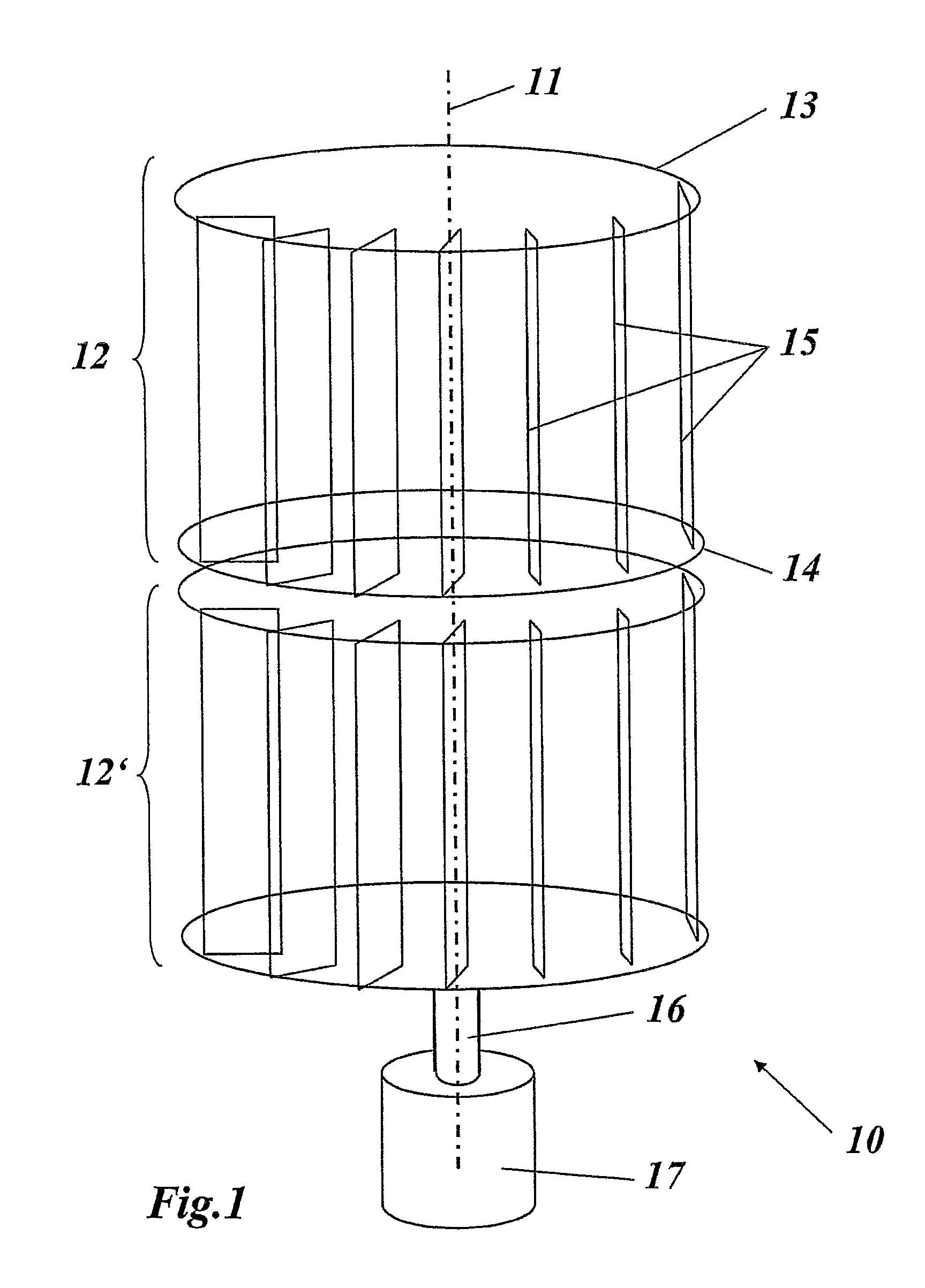
[0039]FIG. 1 shows a highly simplified schematic illustration of a wind power installation in the form of a vertical rotor based on the drag principle and having two rotors one above the other, as is suitable for implementation of the invention. The wind power installation 10 has a vertical axis 11 about which two rotors 12 and 12′ rotate. Further rotors may, of course, also be provided, which rotate about the axis 11. However, it is just as possible to provide only a single rotor 12. The rotor or rotors 12, 12′ is or are connected via a shaft 16 to a generator unit 17, which can also contain a gearbox in order to change the rotation speed. Instead of the shaft 16, a shaft train comprising a plurality of individual shafts located concentrically one inside the other can be provided, via which the individual rotors 12, 12′ are coupled to the generator unit 17 independently of their rotation. This is particularly advantageous when the aim is to optimally tap off flow strata with differ...


PUM


Abstract

The invention relates to a wind power plant, comprising a rotor that can be rotated about a vertical axis, said rotor between two horizontal bearing planes disposed at a distance on top of each other comprising a plurality of rotor blades, which are disposed distributed on a circumferential circle, can each be pivoted about a vertical pivot axis, and the pivot range of which is delimited on both sides by a stop. In such a wind power plant, an improvement in the energy yield, while simultaneously ensuring another operation, is enabled in that the width of the rotor blades is smaller than approximately ⅓ the radius of the circumferential circle.

Description

TECHNICAL FIELD[0001]The present invention relates to the field of alternative energy production by means of wind power.DESCRIPTION OF RELATED ART[0002]Wind power installations, that is to say installations for obtaining (electrical) energy from the wind, have been known for a long time in widely differing forms and embodiments. One fundamental distinguishing feature between such wind power installations, which normally have a rotor which rotates about a rotation axis, is the spatial arrangement of the rotation axis: in the case of so-called vertical rotors, the rotor rotates about a vertical axis, while in the case of horizontal rotors, the rotor rotates about a horizontal rotation axis. Vertical rotors, which also include the wind power installation according to the present invention, have the particular advantage over horizontal rotors that they do not need to be adjusted for a specific wind direction.[0003]In principle, the power contained in the wind at a wind speed v is propor...

Claims


Application Information

Patent Timeline
Patent Type & Authority Patents(United States)
IPC IPC(8): F03D9/00H02P9/04F03B13/00
CPCF03D3/067F03D9/028F03D9/001Y02E10/74Y02E60/15F03D3/02F03D9/17F03D9/28F03D13/20Y02E60/16Y02E70/30
Inventor RICHTER, PATRICKBAHNMULLER, KARL
Owner AGILE WIND POWER
Why Eureka
Try Eureka