Front hand wheel locking linear separation electromagnetic separation mechanism with floating function

A technology of electromagnetic separation and handwheel, which is applied in the direction of circuits, electrical components, coupling devices, etc., can solve the problems of complicated mechanism operation process, prone to misoperation, and high requirements for machining of rod parts

Active Publication Date: 2019-03-29
CHINA AVIATION OPTICAL-ELECTRICAL TECH CO LTD
View PDF11 Cites 1 Cited by
  • Summary
  • Abstract
  • Description
  • Claims
  • Application Information

AI Technical Summary

Problems solved by technology

[0002] The existing electromagnetic separation mechanism has strict requirements on the accuracy of the relative installation position of the connector interface and the mechanism, and cannot realize the floating function. In addition, the driving handwheel is installed at the lower part of the electromagnet, and the rod parts are mechanically required during the large-stroke separation process. High, and the operation process of the mechanism is complicated, and it is prone to misoperation

Method used


Image

  • Front hand wheel locking linear separation electromagnetic separation mechanism with floating function
  • Front hand wheel locking linear separation electromagnetic separation mechanism with floating function
  • Front hand wheel locking linear separation electromagnetic separation mechanism with floating function

Examples


Embodiment Construction

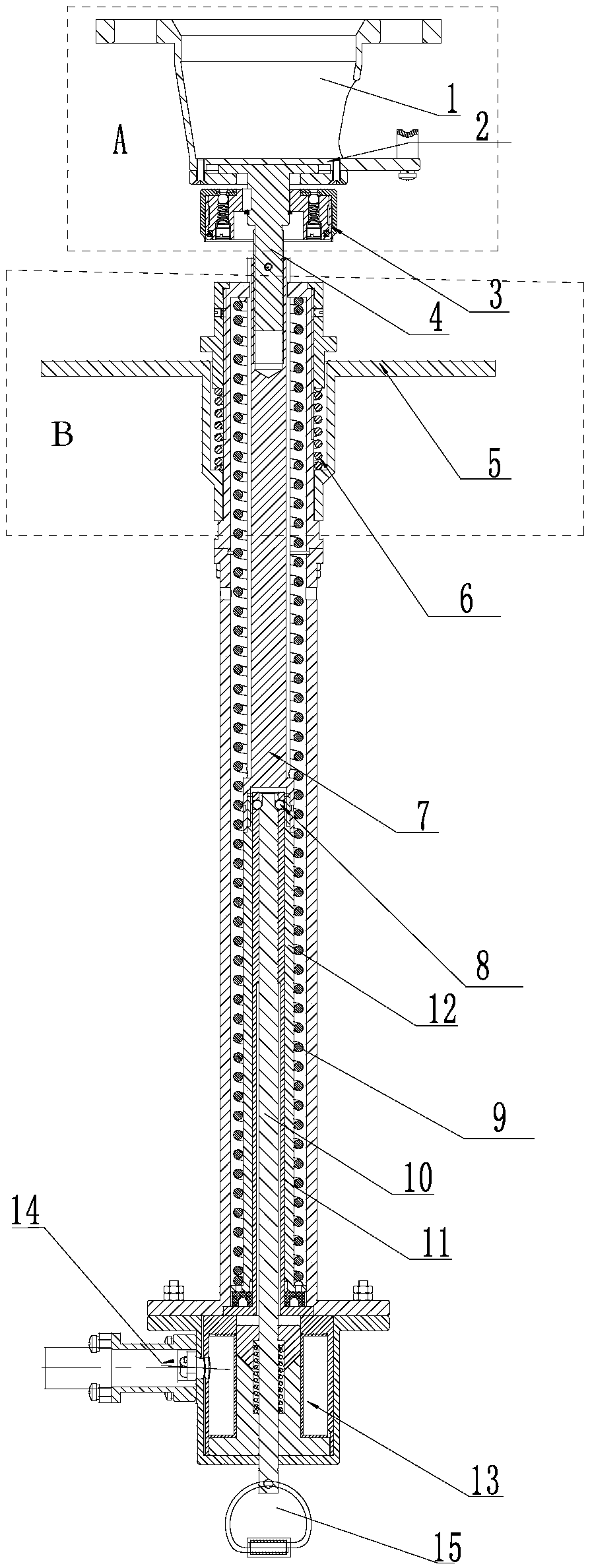
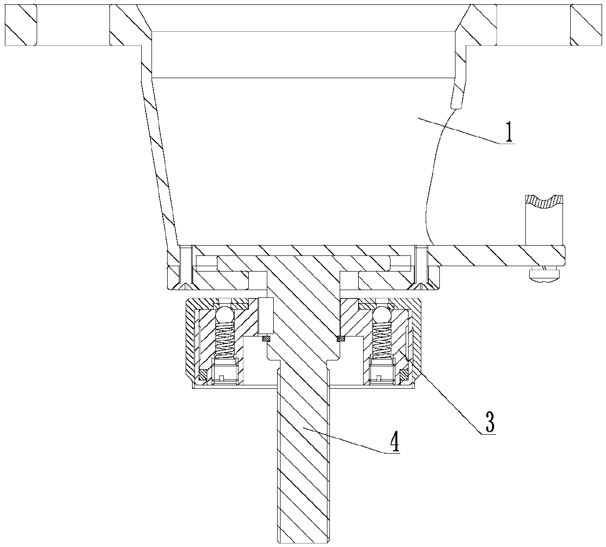
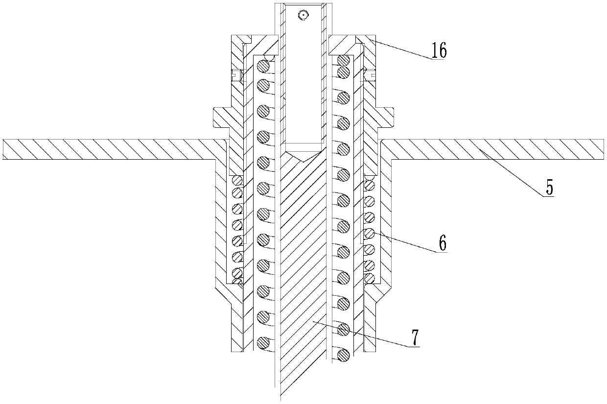
[0032] In order to further explain the technical means and effects that the present invention adopts to achieve the intended purpose of the invention, in conjunction with the accompanying drawings and preferred embodiments, the front handwheel locking linear separation electromagnetic separation mechanism with floating function proposed according to the present invention will be described below. Specific embodiments, structures, features and effects thereof are described in detail below.

[0033] see Figure 1-3 , which is a structural schematic diagram of the front handwheel locking linear separation electromagnetic separation mechanism with a floating function in the present invention. The front handwheel locking linear separation electromagnetic separation mechanism with a floating function includes an electromagnetic separation part and a floating part, wherein the electromagnetic The separation part includes an upper shell and a lower shell, wherein the lower shell is pro...


PUM


Abstract

The invention relates to a front hand wheel locking linear separation electromagnetic separation mechanism with a floating function, which comprises an electromagnetic separation component and a floating component. The top of a pull rod connected to the upper part of a separation sleeve in the electromagnetic separation component extends out of a shell of the electromagnetic separation component,and a bolt hole is arranged in the top of the pull rod. The floating component includes a floating spring, an interface component, a floating bolt, and a hand wheel connected to the floating bolt. A mounting plate sleeves the outer side of the shell of the upper part of the electromagnetic separation component, and the lower end face is stopped on a stopping face outside the shell. A pressing sleeve which sleeves the shell presses the floating spring on the upper end face of the mounting plate. The floating bolt is connected to the interface component, and can float circumferentially relativeto the interface component. The floating bolt is screwed into the bolt hole in the top of the pull rod. The radial and axial floating functions of connectors are achieved. The number of parts is reduced. The difficulty of parts processing is reduced. The operation process is simplified.

Description

technical field [0001] The invention relates to the technical field of electromagnetic separation mechanisms, in particular to an electromagnetic separation mechanism with a floating front hand wheel locking linear separation. Background technique [0002] The existing electromagnetic separation mechanism has strict requirements on the accuracy of the relative installation position of the connector interface and the mechanism, and cannot realize the floating function. In addition, the driving handwheel is installed at the lower part of the electromagnet, and the rod parts are mechanically required during the large-stroke separation process. High, and the operation process of the mechanism is complicated, and it is prone to misoperation. [0003] In view of the above-mentioned defects existing in the existing linear separation and electromagnetic separation mechanism, the inventor, based on his rich practical experience and professional knowledge in the design and manufacture...

Claims


Application Information

Patent Timeline
Patent Type & Authority Applications(China)
IPC IPC(8): H01R13/635
CPCH01R13/635
Inventor 曹德胜庞卓康萌张跃强
Owner CHINA AVIATION OPTICAL-ELECTRICAL TECH CO LTD
Why Eureka
Try Eureka