
Valve position detection method, valve position sensor and valve

A detection method and sensor technology, applied in valve devices, instruments, measuring devices, etc., can solve the problems of high difficulty and cost, difficult to adapt to valves with various structures, etc., and achieve the effect of reducing difficulty and cost

Pending Publication Date: 2019-04-02
黄强
View PDF0 Cites 0 Cited by
  • Summary
  • Abstract
  • Description
  • Claims
  • Application Information

AI Technical Summary

Problems solved by technology

[0003] In the prior art, the valve state can be detected by a valve position sensor including a mechanical contact switch or an electromagnetic proximity switch, but this valve position sensor needs to be customized for the specific structure of the valve, and requires a specific installation position and installation space, which is difficult It is suitable for valves with various structures (especially various manual valves), which makes it difficult and expensive to detect the valve status

Method used


Image

  • Valve position detection method, valve position sensor and valve
  • Valve position detection method, valve position sensor and valve
  • Valve position detection method, valve position sensor and valve

Examples


Embodiment Construction

[0029] The technical solutions in the present disclosure will be clearly and completely described below in conjunction with the drawings in the present disclosure. Obviously, the described embodiments are only some of the embodiments of the present disclosure, not all of them. The components of the present disclosure generally described and illustrated in the figures herein may be arranged and designed in a variety of different configurations. Accordingly, the following detailed description of the present disclosure, provided in the accompanying drawings, is not intended to limit the scope of the claimed disclosure, but merely represents selected embodiments of the present disclosure. Based on the embodiments of the present disclosure, all other embodiments obtained by those skilled in the art without creative effort shall fall within the protection scope of the present disclosure.

[0030] It should be noted that like numerals and letters denote similar items in the following...


PUM


Abstract

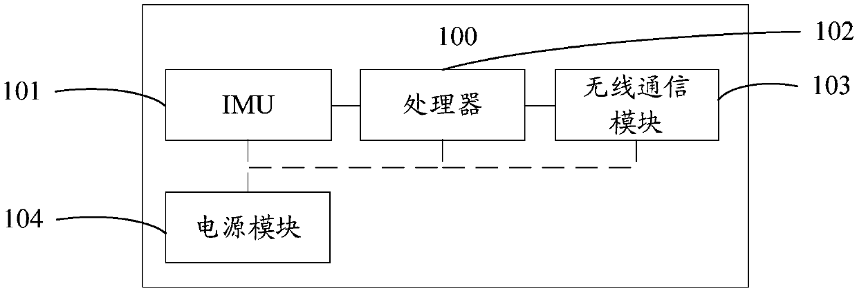
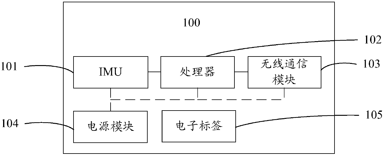
The invention provides a valve position detection method, a valve position sensor and a valve and relates to the technical field of fluid control. The method comprises the steps of detecting motion status data of the valve; determining the current position status data of the valve according to the motion status data; and transmitting the current position status data to a server. Through the valveposition detection method, the valve position sensor and the valve, the status detection difficulty and cost of the valve can be substantially reduced.

Description

technical field [0001] The present disclosure relates to the technical field of fluid control, in particular to a valve position detection method, a valve position sensor and a valve. Background technique [0002] A valve is a device used to control the direction, pressure, and flow of a fluid in a fluid system. It is a device that allows the medium (liquid, gas, powder) in the pipeline and equipment to flow or stop and can control its flow. Valve status is critical to the transmission and control of fluids. [0003] In the prior art, the valve state can be detected by a valve position sensor including a mechanical contact switch or an electromagnetic proximity switch, but this valve position sensor needs to be customized for the specific structure of the valve, and requires a specific installation position and installation space, which is difficult Adapting to valves with various structures (especially various manual valves) makes it difficult and expensive to detect the v...

Claims


Application Information

Patent Timeline
IPC IPC(8): F16K37/00G01D21/02
CPCF16K37/0041G01D21/02
Inventor 黄强
Owner 黄强
Features
  • Generate Ideas
  • Intellectual Property
  • Life Sciences
  • Materials
  • Tech Scout
  • Unparalleled Data Quality
  • Higher Quality Content
  • 60% Fewer Hallucinations
Learn More