A switch cabinet temperature and humidity monitoring system

A monitoring system and switch technology, applied in control/regulation systems, non-electric variable control, simultaneous control of multiple variables, etc., can solve problems such as inability to precisely control, and achieve the effects of uncomplicated mechanism, good cooling effect and low cost

Active Publication Date: 2020-11-10
HENAN POLYTECHNIC INST
View PDF2 Cites 0 Cited by
  • Summary
  • Abstract
  • Description
  • Claims
  • Application Information

AI Technical Summary

Problems solved by technology

This application also cannot be precisely regulated after monitoring the temperature and humidity

Method used


Image

  • A switch cabinet temperature and humidity monitoring system
  • A switch cabinet temperature and humidity monitoring system
  • A switch cabinet temperature and humidity monitoring system

Examples


Embodiment 1

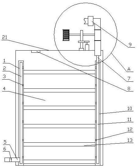
[0029] Embodiment 1, the present invention provides a switch cabinet temperature and humidity monitoring system, including a cabinet 4, a first vertical board 10 and a second vertical board 1 arranged on both sides inside the cabinet 4, and a first vertical board 10 and a second vertical board 1 Several layers of horizontal partitions 13 between the two vertical boards 1, a temperature and humidity monitoring mechanism is set up and down inside the first vertical board 10, and an air supply mechanism is provided on the first vertical board 10 corresponding to the horizontal partitions 13 of each layer, The second vertical plate 1 is provided with an exhaust mechanism corresponding to the horizontal partition 13 of each floor, and a dehumidification mechanism is arranged on the air supply mechanism. Air mechanism and the control mechanism 8 that dehumidification mechanism signal is connected.

[0030] There are many horizontal partitions in the switch cabinet, and the tradition...

Embodiment 2

[0034] The difference between this embodiment and Embodiment 1 is:

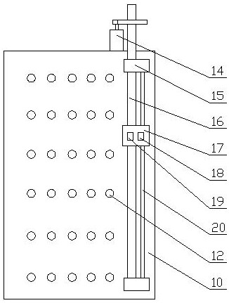
[0035] The lifting mechanism includes mounting blocks 15 arranged at the upper end and the lower end of the first riser 10, and a lifting lead screw 16 is rotated between the two mounting blocks 15, and the lifting screw 16 is also arranged between the two mounting blocks 15. 16 parallel guide rods 20, the lifting slider 17 is set on the lifting screw 16 and the guiding rod 20, the infrared temperature sensor 18 and the humidity sensor 19 are arranged on the lifting slider 17, the lifting screw 16 The upper end passes through the mounting block 15 and is in drive connection with the lifting motor 14 arranged on the upper part of the first riser 10 , and the lifting motor 14 is signal connected with the control mechanism 8 .

[0036] The mounting block is used to set the lifting screw and the guide rod, and the lifting slider has an internal thread hole for the lifting screw, so that when the lifting motor dri...

Embodiment 3

[0038] The difference between this embodiment and Embodiment 1 is:

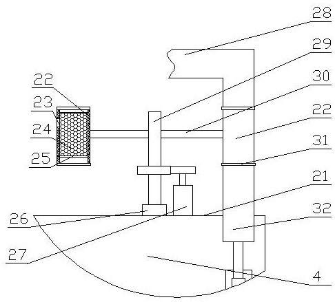
[0039] The air supply mechanism includes a first vertical plate 10 with a first cavity 11 inside, and several rows of air outlet holes 12 are arranged on the inner side of the first vertical plate 10 corresponding to the transverse partition plate 13, and the air outlet holes 12 are connected to the first cavity. The cavity 11 communicates, and the upper end of the first cavity 11 communicates with the air supply duct 7, and the electromagnetic valve 9 is arranged on the air supply duct 7, and the electromagnetic valve 9 and the first cavity 11 are connected between the The dehumidification mechanism is arranged on the air supply pipe 7 , and the electromagnetic valve 9 is connected with the control mechanism 8 by signals. The air supply duct sends the cold air into the first cavity, and under the action of pressure, it is sprayed out through the air outlet holes. A row of air outlet holes is set for each swi...


PUM


Abstract

The invention provides a switch cabinet temperature and humidity monitoring system. The switch cabinet temperature and humidity monitoring system comprises a cabinet, a first vertical plate, a secondvertical plate and a plurality of layers of diaphragm plates, wherein the first vertical plate and the second vertical plate are arranged on two sides inside the cabinet; the plurality of layers of diaphragm plates are arranged between the first vertical plate and the second vertical plate; a temperature and humidity monitoring mechanism is arranged on an inner side of the first vertical plate inan ascending-descending manner; air blowing mechanisms are arranged on the first vertical plate corresponding to each layer of diaphragm plate; air-releasing mechanisms are arranged on the second vertical plate corresponding to each layer of diaphragm plate; and the air blowing mechanisms are provided with dehumidifying mechanisms. Through adoption of the switch cabinet temperature and humidity monitoring system, the temperature and humidity in the switch cabinet can be monitored and controlled in order to keep proper temperature and humidity in the working environment of a switch. Meanwhile,a cooling mechanism is used for cooling each switch, so that a better cooling effect is achieved. Moreover, the overall mechanism is uncomplex, and the cost is very low.

Description

technical field [0001] The invention relates to the technical field of switch cabinets, in particular to a temperature and humidity monitoring system for switch cabinets. Background technique [0002] A switch is a network device used for electrical (optical) signal forwarding. It can provide an exclusive electrical signal path for any two network nodes connected to the switch. The most common switches are Ethernet switches. Other common ones are telephone voice switches, fiber optic switches, etc. The switch is generally installed in the switch cabinet. The switch cabinet is mainly set up to save space and support the switch. Most of the existing cabinets include a shell and several layers of horizontal plates arranged in the shell. The switch is set on the horizontal plate. However, if a large number of switches are installed together, a lot of heat will be generated. At present, most of the heat generated by the switches is solved by setting a central air conditioner i...

Claims


Application Information

Patent Timeline
Patent Type & Authority Patents(China)
IPC IPC(8): G05D27/02
CPCG05D27/02
Inventor 马磊娟王磊赵冉张勇赵国萌丁祎刘宇通景迪
Owner HENAN POLYTECHNIC INST
Why Eureka
Try Eureka