
Method for inhibiting converter overload by flexible direct current transmission bipolar system

A flexible DC transmission and converter technology, which is applied in AC network circuits, photovoltaic power generation, wind power generation, etc., can solve the problems of bus power loss, power transfer, DC overvoltage, etc., and achieve the effect of avoiding overload shutdown

Active Publication Date: 2019-04-02
NR ELECTRIC CO LTD +1
View PDF4 Cites 0 Cited by
  • Summary
  • Abstract
  • Description
  • Claims
  • Application Information

AI Technical Summary

Problems solved by technology

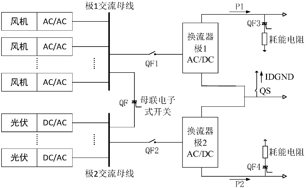
[0004] The bipolar system structure of flexible direct current transmission realizes that when renewable new energy is sent out from an isolated island, new energy sources such as wind power and photovoltaics are connected to the AC bus at multiple points, and the bipolars are connected to the AC bus. If the bipolar buses are not connected, the power of the two poles is unbalanced. , there is a large current problem in the grounding pole of the inverter. In addition, when one pole of the inverter fails, the power of the busbar connected to this pole will be completely lost, and the effective transmission of new energy cannot be realized.
If the bipolar bus is directly connected without control, when one pole fails, the other pole will have the risk of overload and outage due to power transfer
In addition, when a fault occurs outside the converter area at the sending end, the power cannot be sent out, and DC overvoltage problems will occur at the corresponding fault pole.

Method used


Image

  • Method for inhibiting converter overload by flexible direct current transmission bipolar system
  • Method for inhibiting converter overload by flexible direct current transmission bipolar system

Examples


Embodiment Construction

[0025] The technical solutions of the present invention will be described in detail below in conjunction with the accompanying drawings and specific embodiments.

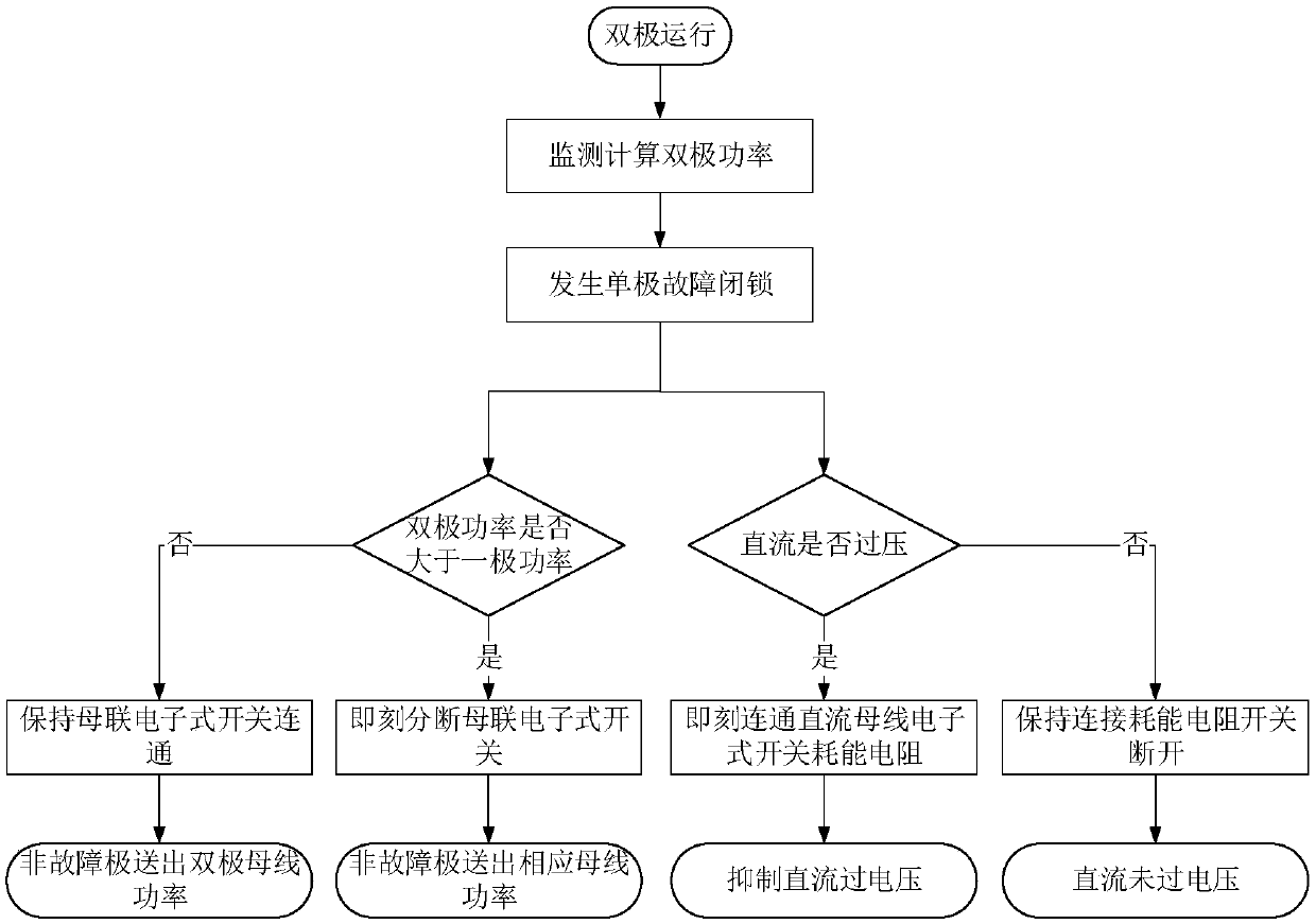
[0026] figure 1 It is a schematic diagram of adding electronic switches and energy-consuming devices to the flexible DC transmission bipolar system in the present invention, that is, adding QF bus-connected electronic switches to connect between pole 1 AC bus and pole 2 AC bus, and adding QF3 electronic switches to pole 1 The switch is connected to the energy consumption resistance device, and a QF4 electronic switch is added to the pole 2 to connect the energy consumption resistance device. figure 2 It is a schematic diagram of a method for suppressing the overload of a converter in a flexible direct current transmission bipolar system of the present invention, and the specific method includes the following:

[0027] (1) The bipolar AC side of the converter is connected to the AC bus, and the bus-connected electr...


PUM


Abstract

The invention provides a method for suppressing overload of a converter by a flexible direct current transmission bipolar system. For an island passive system connected to the new energy access, the two poles of the alternating current side of a bipolar converter are respectively connected with separated alternating current buses, the buses at the two poles employ electronic switch devices as female connection switches, the converter is in bipolar operation, the female connection electronic switches communicate, when one pole is locked, when it is monitored that the bipolar power is larger than the maximum power limit of one pole of the converter, the female connection electronic switches are disconnected, and when the bipolar power is smaller than the maximum power limit of the pole, theelectronic switch turn-on state is kept. Besides, aiming at the fault problem from the direct current circuit of the converter to the receiving end of the converter, connected energy consumption resistance devices through the electronic switches are added on the positive and negative direct current buses, and the electronic switch input energy consumption resistance device is turned on when the direct current overvoltage is detected to inhibit the overvoltage of the converter.

Description

technical field [0001] The invention belongs to the field of flexible power transmission in electric power systems, and in particular relates to a method for suppressing the overload of a converter in a bipolar system of flexible direct current transmission. Background technique [0002] Flexible DC transmission uses voltage source converters, which can independently adjust the output of active and reactive power, improve the transmission capacity of the AC system, and easily form a multi-terminal DC transmission system. And other application fields, with obvious competitiveness. With the advancement of power electronic devices and control technology, the capacity and voltage level of flexible direct current transmission system are getting higher and higher. [0003] In order to meet the requirements of large-capacity power transmission, it is necessary to increase the number of sub-modules to increase the voltage level, but the cascading of too many sub-modules increases t...

Claims


Application Information

Patent Timeline
IPC IPC(8): H02J3/36H02J3/38
CPCH02J3/383H02J3/386H02J3/36Y02E10/56Y02E10/76Y02E60/60
Inventor 随顺科胡兆庆卢宇董云龙李钢汪楠楠王柯
Owner NR ELECTRIC CO LTD
Learn More