

Motor and air-conditioning device
A technology of electric motors and power supplies, applied in electromechanical devices, manufacturing motor generators, air-conditioning systems, etc., can solve problems such as the limitation of the number of substrates, achieve the effect of increasing the number of acquisitions and reducing manufacturing costs
- Summary
- Abstract
- Description
- Claims
- Application Information
AI Technical Summary
Problems solved by technology
Method used
Image

Examples
Embodiment approach 1
[0032]
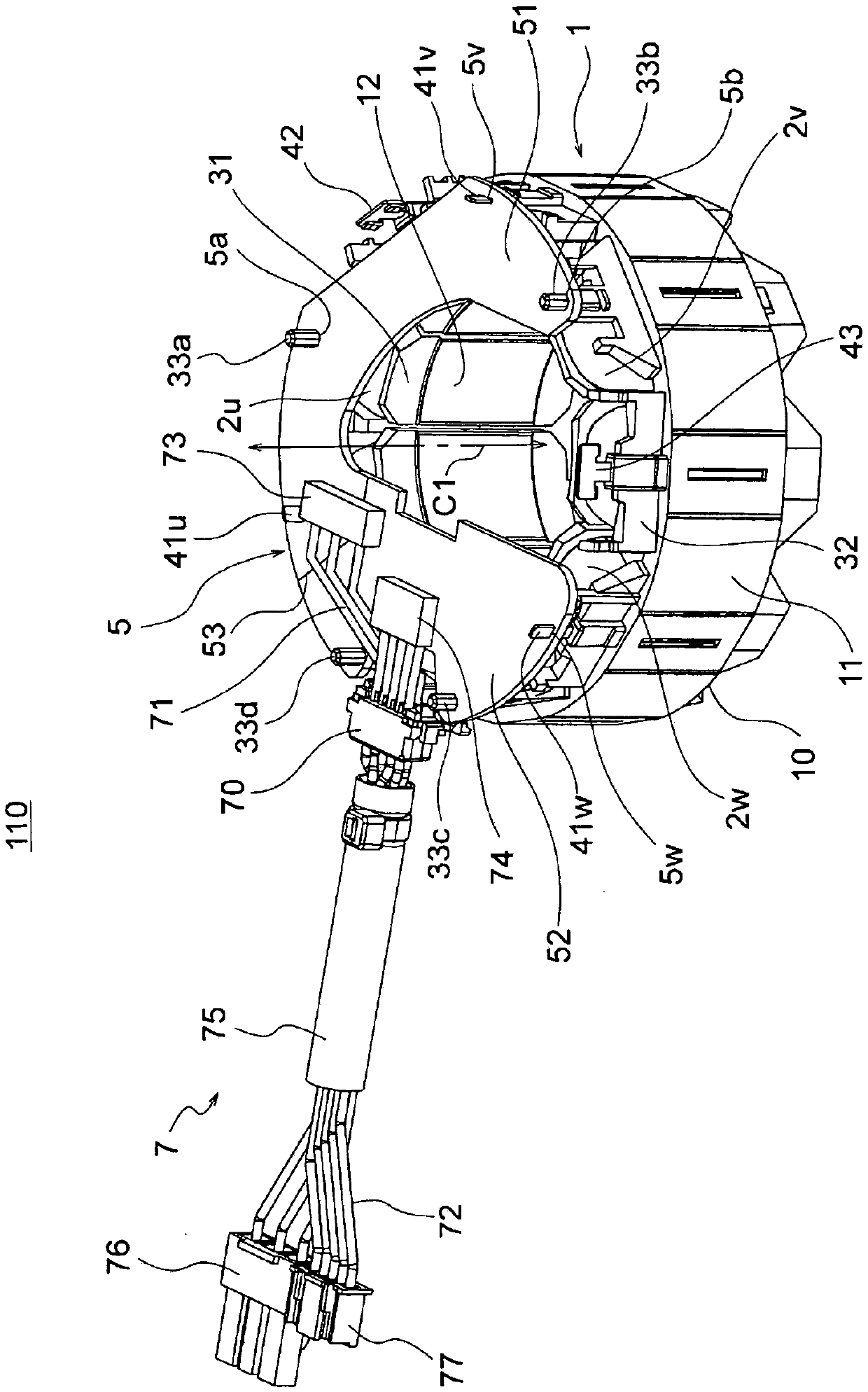
[0033] figure 1 It is a perspective view showing the structure of the stator assembly 110 according to Embodiment 1 of the present invention.
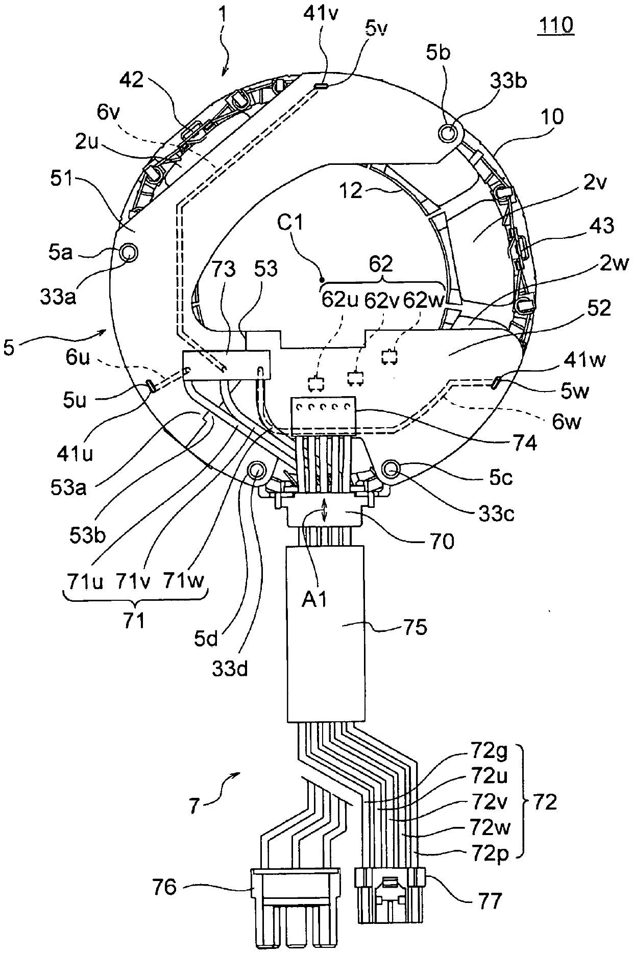
[0034] figure 2 is a plan view showing the structure of the stator assembly 110 . The stator assembly 110 includes a stator 1 , a substrate 5 attached to the stator 1 , and a lead wire group 7 connected to the substrate 5 .
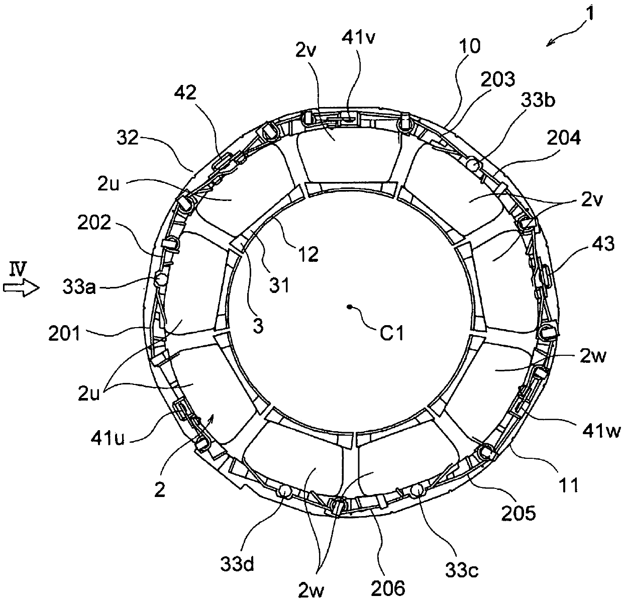
[0035] The stator 1 includes an annular stator core 10 , an insulator (insulation portion) 3 arranged on the stator core 10 , and a coil 2 wound around the stator core 10 . Hereinafter, the direction of the axis C1 forming the center of the ring-shaped stator 1 is simply referred to as "axial direction". In addition, the circumferential direction around the axis C1 is simply referred to as "circumferential direction". The radial direction centered on the axis C1 is simply referred to as "radial direction".
[0036] The base plate 5 is disposed on one axial side of the stator core 10 ( figure 1 In...
Embodiment approach 2
[0115] Next, Embodiment 2 of the present invention will be described. Figure 13 (A) is a plan view showing the stator assembly 111 according to the second embodiment. In this second embodiment, the first substrate 51 and the second substrate 52 are connected using the substrate holding member 9 disposed on the first substrate 51 and the second substrate 52 .
[0116]
[0117] The substrate pressing member (coupling member) 9 has a plurality of ribs 90 extending in a frame shape in a plane perpendicular to the axial direction, and a side opposite to the stator 1 from the ribs 90 ( figure 1 A plurality of protrusions 92 protruding from the upper side in the middle). The substrate holding member 9 is formed of resin such as PBT, for example.
[0118] The rib 90 has a rib 90 a extending along the inner peripheral end of the first substrate 51 , a rib 90 b extending along the outer peripheral end of the first substrate 51 , and a rib 90 b extending along the inner peripheral e...
Embodiment approach 3
[0139] Next, Embodiment 3 of the present invention will be described. Figure 15 It is a plan view showing the structure of the substrate 501 according to the third embodiment. The substrate 5 of Embodiment 1 described above is divided into a first substrate 51 and a second substrate 52 . In contrast, the substrate 501 of Embodiment 3 is divided into a first substrate 51 and a second substrate 52 , and the first substrate 51 is divided into substrates 51A and 51B.
[0140]
[0141] The substrate 51A (first substrate) is configured to include the U-phase power supply wiring 6u and the terminal insertion hole 5u. The substrate 51B (third substrate) is configured to include the V-phase power supply wiring 6v and the terminal insertion hole 5v. In addition, the base plate 51A has pins 33a ( figure 2) engagement hole 5a, the substrate 51B has a pin 33b with the stator 1 ( figure 2 ) engaging hole 5b for engaging.
[0142] A connecting portion 56 (division surface) is forme...
PUM
 Abstract
Description
Claims
Application Information